diy solar

diy solar

Need help with A/C Neutral and Ground w/Growatt inverter...

Digging didn't turn up anything, but the mobile home it was feeding does have a ground rod and its service panel had the ground separated from the neutral bus bar.
Interesting...

1) No N-G bond at the house
2) No Equipment Grounding Conductor from the monument to the house...

Is that correct?

That seems wrong. There would be no low-impedance path to clear faults.
 
Been following this thread with interest since my service also starts with a pedestal, which is then split into two feeds of 3 wire triplex feeding 1) a shop, 2) the house. Let's just say, I am all kinds of kornfused. The triplex is only three wires so there is no ground wire to connect the feeder? panels with the pedestal. Not sure about the house or pedestal, yet. Is it safe to only have three wires from the pedestal to the other panels?

There isn't a bare ground wire in the trench? Is this direct burial or in conduit?
 
@FilterGuy and I have been chatting for quite a while. I'm sure he is way past tired of dealing with me. He says it is reasonably safe, not the way it would be done today, but safe. He listed things like a feeder that includes a ground, better earth ground than a pedestal, isolate neutral and ground at both shop and house, and grounding electrodes at shop for some improvements. He also said to say there is a n-g bond at the house and shop.

I have to give a big thank you to @FilterGuy In this world of today, full of armchair warriors, divisiveness, and political agendas, it's awesome to have a knowledgeable person lending a helping hand. It is appreciated. Maybe, if I don't electrocute myself first, I can pay it forward.
 
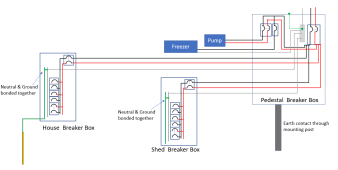
@Kornbread 's system looks like this:
1643600041739.png
Since there are no grounds running from the pedestal to the shed or the house, there are N-G bonds at the shed and house. This works because without the ground wires back to the pedestal the bonds are separated. Kornbread is going to work on the grounding for the pump and freezer but other than that I can't see any safety issues.
 
The AWA gave the green light and a pair of eg4 batteries are due in this week, but somethjing has me worried. The growatt spf6000t dvm has grid assist, and I think it will come in handy ... but grounding. Since the input from grid to the growatt is 240v, it will need both hots and the neutral, which is bonded w/ground at the shop panel (^see post #44).

How should I go about grounding the growatt?

And in relation to the pv panels, do the panels get grounded and that ground runs along with the home from panels to the growatt?
 
Last edited:
can I do a single 30A 120v grid input to charge my batteries? or does it has to be both lines of 120v each for my growatt 12kw inverter
 
I read this entire thread and alot was above me but I am learning.
I loved the drawings/schematics but was wondering if you have any drawings that I could use for a Growatt 12K all inn one
that will be connected to the house grid for charging and pass thru purposes. I only have one main electrical 200amp panel
to connect to
Thanks
Hi! Are you happy with your Growatt so far? Did you settle with common neutral? Thanks!
 
Hi! Are you happy with your Growatt so far? Did you settle with common neutral? Thanks!
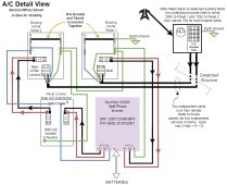
Hi, As the original poster to this thread, I can say that I've been very happy with the Growatt inverter. It's been running now for about 8 months 24x7. Every day, it's used for charging a PHEV (plug-in hybrid car) and keeping a garage refrigerator and a stand-alone freezer running. In power failure mode it can feed much of the house's power (Panel 2) excluding things like the heat pump, dryer, oven, etc (Panel 1). When there has been inadequate solar, it switches to bypass mode and draws power from panel 1 for meeting its load. After much thought and discussion with SS, I went with the neutral and grounds the way I originally drew it. Here is the latest drawing with a few tweaks for clarity.
 

Attachments

  • A_C wiring.jpg
    A_C wiring.jpg
    109.3 KB · Views: 10
Back
Top