diy solar

diy solar

Need some help with connecting to ground for my inverter!

Neutral to Ground is giving me ~100V AC. The output however is 230V AC?
That tells us that the output of the inverter is floating.

Is this what I should be doing? i.e. ignore the utility, but connect the Earth and Negative into the AC output breaker...

This way any grounding fault will draw a high current over the earth wire and trip the breaker?

Also connecting a earthing rod as an additional layer of protection (although not actually sure if that's needed?!?!)

View attachment 76546
(excuse the scrawl!)
Note: not sure what to do with the utility ground input.
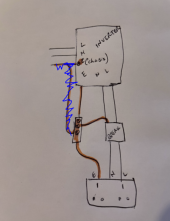
I would not add another ground rod. Instead, I would tie the ground you show to the ground system of the rest of the house. (Having two separate points the system ties to earth ground can create it's own problems.

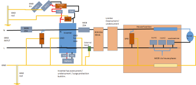
I like the idea of adding the bond as shown in your diagram but.... there are some inverters that do not support bonding on the output. You should probably contact the manufacturer to see what they say.

In addition, if you ever run the inverter in pass-through mode, having the bond on the output will become a 2nd bond.... and current will flow on the PE wire.... this is generally considered a bad thing. In the diagram below the purple dash is the 'normal' current flow and the red dash is the 'bad' current flow on the PE wire.

1640047725119.png

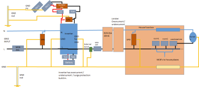
The alternative is to leave the output floating. As I said earlier, some people on the forum are OK with floating outputs. Since there is no tie between the earth and hot, you should not get shocked even if you touch the hot wire. The only way to get shocked is to touch both the hot and neutral wire.
 
@FilterGuy makes perfect sense. I have no idea why the manual is so blasé about this. There is so much more than meets the eye and there is no mention on this bond!

I have gone ahead and added the bond as per this diagram:
IMG_3017.jpeg

My socket tester is now showing a correct ground!!
Also the RCD breaker now trips when I press the RCD test button (it didn't before), so if nothing else this is a positive move.

The bit I am still not clear on is the connection of the Utility Earth to the same Earth bar. Does it not cause any issue having a shared Neutral (and Earth), on 2 separate circuits? I noticed when connecting the Utility Earth there was a small spark implying there was some current pass. I presume if I don't connect that it will still work OK, although there would be no earth ground I presume? Keen to hear your thoughts?

On a separate note, for grounding my panels, I presume the best thing is just ground them directly to an earth bar to give me some lightning protection and nothing more is needed?
 
Post # 13. That is just wrong. Don't think that way.
Have learnt a lot about grounding and earths over the last couple of days. It makes total sense about the earth and neutral bond now but know the way i was thinking in #13 it totally off.

I always through that earth was used to 'dissipate' energy (in the ground), however now see that its actually a way to safely complete a circuit in the fastest possible way... to trip the breaker and cut the power. By making it just as quick if not quicker as the neutral it make this process happen quickly. o_O
 
The bit I am still not clear on is the connection of the Utility Earth to the same Earth bar. Does it not cause any issue having a shared Neutral (and Earth), on 2 separate circuits? I noticed when connecting the Utility Earth there was a small spark implying there was some current pass. I presume if I don't connect that it will still work OK, although there would be no earth ground I presume? Keen to hear your thoughts?
Sorry..... I am not following the question. Could you ask in a different way?
On a separate note, for grounding my panels, I presume the best thing is just ground them directly to an earth bar to give me some lightning protection and nothing more is needed?
REMINDER: I am in the states and the rules/standards may be different in the UK.

1st: There is no grounding scheme that will protect from a direct lightning strike A direct strike is going to destroy things and there is nothing grounding can do to protect it. However, grounding the frames is still important in order to dissipate static charges that can build up. When doing the grounding, it is important to minimize issues due to nearby lightning strikes.

I would not do a separate earth bar. I would tie the panel frames to the same earth ground as the rest of the system.

1640105165763.png


If you add a grounding rod for the frames but do not connect it to the house earth grounding, it is not quite as bad, but you can still generate significant voltage potentials between the PV wiring and the frame. These potentials can be high enough to arc and cause damage.
 
Connecting the metal solar panel frames to ground rods make a poor version of Franklin's Rod. The effect is to bleed the static and avoid a large potential between the frame and atmosphere. It would work better to have a sharp pointed brass spike at the top.
 
Connecting the metal solar panel frames to ground rods make a poor version of Franklin's Rod. The effect is to bleed the static and avoid a large potential between the frame and atmosphere. It would work better to have a sharp pointed brass spike at the top.
Earth-Grounding the frames of the panels is NOT trying to create a lightning protection system. A lightning protection system with lightning rods/franklin rods is a totally separate system that is completely independent of the electrical earthing system of a building. There is a whole science around where to place the lightning rods and how to ground them in order to create a zone that is less likely to be struck by lightning. Mixing a lightning protection system and the electrical grounding system is a really bad idea.
 
Sorry..... I am not following the question. Could you ask in a different way?

I just mean what's the advantage of connecting the utility earth to the invertor earth, sine it would trip either way. Also it prevents bypass from working?
 

Attachments

  • aaa.PNG
    aaa.PNG
    270.6 KB · Views: 9
I just mean what's the advantage of connecting the utility earth to the invertor earth, sine it would trip either way. Also it prevents bypass from working?

OK...now I understand. Good question.

With the diagram as shown here, the inverter and it's case would be independent of the Utility grounding system.
1640117350528.png

If something were to happen internal to the inverter and the utility Line shorted to the case, there would be nothing to clear the fault (Pop the breaker).

Now let's look at the earlier design with the ground rod. Would that solve the problem?

1640117559666.png

I believe in England, resistance to the ground of 20 ohms is considered good. However, it is very likely that over time that resistance will go up.

Let's use the 20 ohms and also assume 20 ohms at the utility grounding. That means there are 40ohms from the hot, through the ground back to the utility neutral. A short circuit to earth-ground would create 240V/40ohms=6Amps. This would not be enough to trip a regular breaker, but if you had an RCD someplace in the path it would trip. So, to make the design safe, an RCD is needed before the inverter.

However, let's look at what happens when the inverter is in pass-through mode with the above circuit

1640118843625.png

Notice that some of the current that is supposed to flow through the neutral will find its way back to the source via the earth. The earth resistance will be very high compared to the resistance through the neutral line, so the current through the earth will be small.... but it does not take much earth/ground current to pop an RCD. (I believe RCDs in the UK will operate at either 30ma or 100ma). Even if you hook it all up and find that it works, there is a really good chance you will get nuisance trips every once in a while.
 
It would not be my favorite solution, but one possible solution is this:

1640121425352.png

In pass-through mode it will look like this

1640121255505.png

Notice that anyplace a short could occur, either a regular breaker or an RCD would pop.

Now lets look at the situation when the inverter is powering off the battery.


1640121529550.png

In this case, the output is floating. (there is no connection between the output neutral and PE). Lets look a a few fault scenarios to see if this is ok.

1) Short between Hot and Neutral - The breaker will pop and clear the fault.
2) Short between Neutral and ground - Theoretically, there is no path back to the hot line so there should be no current.
3) Short between Hot and ground - Theoretically, there is no path back to the neutral line so there should be no current.

HOWEVER: As you have observed, there is a voltage potential of 100V between Neutral and PE. This is due to some amount of capacitive or inductive coupling to the ground in the inverter. That means there will be SOME current if there is a connection between either hot and ground or Neutral and ground. The amount of current will depend on the amount of coupling typically and will typically be small. However, I have seen cases where the current was high enough to cause a tingling sensation. Because of this, I would advise making the breaker after the inverter an RDC breaker.


As I said before, this is not my preferred solution. I prefer to never have a floating circuit. Unfortunately, the inverter instructions do not tell us enough to know how to do that.

In My Opinion, the best way to deal with this is to have the inverter create the N-G bond whenever it is in inverter mode and remove it when not in inverter mode..... but it does not appear your inverter will do that.
 
WARNING: THE FOLLOWING MAY BE A REALLY BAD IDEA WITH YOUR INVERTER. I offer it as something to ask your inverter manufacturer about.

There have recently been several threads about the same problem with grounding the older Growatt inverters. The solution turned out to be to make a connection from AC Neutral out to AC Neutral IN.

1640123225295.png

NOTE: A GFCI is the US equivalent of a RCD. Some GFCI plugs will disconnect both the line and Neutral. If there is a GFCI in front of the inverter that disconnects the neutral, the bonding relay is needed.
 
  • Like
Reactions: JAS
wow amazing responses @FilterGuy !!!

Notice that some of the current that is supposed to flow through the neutral will find its way back to the source via the earth. The earth resistance will be very high compared to the resistance through the neutral line, so the current through the earth will be small.... but it does not take much earth/ground current to pop an RCD. (I believe RCDs in the UK will operate at either 30ma or 100ma). Even if you hook it all up and find that it works, there is a really good chance you will get nuisance trips every once in a while.

Makes perfect sense. I do actually have an RCD on the inverter input, since it comes from the main fusebox with both an MCB and and RCD. That said am keen to avoid nuisance trips, and also don't like the idea of current passing through earth

It would not be my favorite solution, but one possible solution is this:

View attachment 76631

This is actually the way I originally thought this would work, and had it wired, however I was getting a ground fault on the Load because it was floating (at least when running via the battery, I have not tested with bypass on).

OWEVER: As you have observed, there is a voltage potential of 100V between Neutral and PE. This is due to some amount of capacitive or inductive coupling to the ground in the inverter. That means there will be SOME current if there is a connection between either hot and ground or Neutral and ground. The amount of current will depend on the amount of coupling typically and will typically be small. However, I have seen cases where the current was high enough to cause a tingling sensation. Because of this, I would advise making the breaker after the inverter an RDC breaker.
I do actually have a 30mA RCD on the invertor output also its a 1P+N, but again not happy with a ground fault on the load.

I think the best thing to do is simply not use bypass for me. I am however intrigued what actually happens when I turn bypass mode on! I guess I could add a breaker between the Invertor Ground and the Utility ground, and ensure I switch it whenever I turn on bypass? (although in some cases that is meant to happen automatically when the load exceeds the rated output)

Still blows my mind how the manual says just connect to ground and nothing more on the subject!
 
Still blows my mind how the manual says just connect to ground and nothing more on the subject!
I agree, As you have learned over the past few days, this is not a simple topic and it certainly is not intuitive. I consider it almost criminal that so many inverter manufacturers just ignore such a critical aspect of system safety.
 
It would not be my favorite solution, but one possible solution is this:

View attachment 76631

In pass-through mode it will look like this


Notice that anyplace a short could occur, either a regular breaker or an RCD would pop.

Now lets look at the situation when the inverter is powering off the battery.


In this case, the output is floating. (there is no connection between the output neutral and PE). Lets look a a few fault scenarios to see if this is ok.

1) Short between Hot and Neutral - The breaker will pop and clear the fault.
2) Short between Neutral and ground - Theoretically, there is no path back to the hot line so there should be no current.
3) Short between Hot and ground - Theoretically, there is no path back to the neutral line so there should be no current.

HOWEVER: As you have observed, there is a voltage potential of 100V between Neutral and PE. This is due to some amount of capacitive or inductive coupling to the ground in the inverter. That means there will be SOME current if there is a connection between either hot and ground or Neutral and ground. The amount of current will depend on the amount of coupling typically and will typically be small. However, I have seen cases where the current was high enough to cause a tingling sensation. Because of this, I would advise making the breaker after the inverter an RDC breaker.


As I said before, this is not my preferred solution. I prefer to never have a floating circuit. Unfortunately, the inverter instructions do not tell us enough to know how to do that.

In My Opinion, the best way to deal with this is to have the inverter create the N-G bond whenever it is in inverter mode and remove it when not in inverter mode..... but it does not appear your inverter will do that.

Wondering
Main power input directly connected to inverter. What is the risk if permanent bonding is after inverter. In front of inverter RCD(FI relay) + SPD + MCB. Inverter also connected to ground.
Electricity always try to return to source or everywhere depending on resistance. is what I know. Our power source is the inverter... Grid, PV, battery are components.

I would highly appreciate an opinion.

I am referring what if I do this? Inverter has all kind of protection build in

1675888673787.png
 

Attachments

  • 1675886867623.png
    1675886867623.png
    54.3 KB · Views: 11
  • 1675887244180.png
    1675887244180.png
    53.6 KB · Views: 7
  • 1675887357925.png
    1675887357925.png
    53.6 KB · Views: 9
  • 1675887644266.png
    1675887644266.png
    53.9 KB · Views: 11
Last edited:
not sure other people are aware but there is easy solution in case you do not use inverter can bus ( RS232 ) for anything else.
In case you use Chinese inverters, EASUN &CO, MPP, etc..etc.. Voltacon,,..
If you open inverter the the CPU board has the manufacturer all EASUN have Victron energy ..boards. on communication side all the same at this level.
1675934339900.png

get a box can not be easier and cheaper.
 
This box counts on having a dry-contact that controls the external box. Most of the inverter companies that used to have programming for the dry contact control have removed it and repurposed the dry contact output for other functions.
 
Is this what I should be doing? i.e. ignore the utility, but connect the Earth and Negative into the AC output breaker...

This way any grounding fault will draw a high current over the earth wire and trip the breaker?

Also connecting a earthing rod as an additional layer of protection (although not actually sure if that's needed?!?!)

View attachment 76546
(excuse the scrawl!)
Note: not sure what to do with the utility ground input.
is this will work fine!!!
 
Back
Top