diy solar

diy solar

Need to bond neutral + ground for off grid shed using PIP 3048LV-MK 48V 3kW 120V Inverter

hondaman82

New Member
Joined
Jan 13, 2021
Messages
58
Hello experts,
I am in the middle of connecting the MPPSolar PIP 3048LV-MK 48V 3kW 120V Inverter to a small off grid panel for the tool shed but got stuck on whether or not to bond the neutral and ground ? I saw a video from Will showing that he bond N and G but he is using 240V split phase, I am planning to use just 120V single phase. Please advise is it required to bond N + G? thank you very much!
 
The MPP units will generate a N-G bond when they are on battery but not when they are in pass-through mode.

Without knowing more about your plans it is hard to be definitive, but the general answer to your question is: No, do not put an N-G bond on the output of the 3048LG.

Will the grid be feeding the input of the inverter or is it completely off grid?

Do you plan to have a transfer switch before your load panel to select between the grid and the inverter output? If so, make sure you select a transfer switch that switches neutral as well as hot.
 
Hi FilterGuy,
thank you for your fast response, my set up is completed off grid, only power using either solar panels or 48V batteries, it look pretty much like the screenshot attached with the MPP and a small sub-panel (not connected to house main panel), but I see Will bond N+G, that's why I was a bit confuse whether I need to bond or not
 

Attachments

  • Capture.JPG
    Capture.JPG
    56 KB · Views: 21
Hi FilterGuy,
thank you for your fast response, my set up is completed off grid, only power using either solar panels or 48V batteries, it look pretty much like the screenshot attached with the MPP and a small sub-panel (not connected to house main panel), but I see Will bond N+G, that's why I was a bit confuse whether I need to bond or not
Since it is completely off-grid, The AC will always be powered from the batteries and the MPP will automatically do the N-G bond (You don't need to) However, the MPP assumes that any source that is put on the AC input has an N-G bond. Consequently, if you ever add a generator, you will want to be sure there is an N-G bond on it.

Could you please provide a link to the video from @Will Prowse that you are referring to? Is the video talking about the pip 3048lv-MK?
I see the NG bond in the picture and I am a little surprised by it. If the MPP is also providing an N-G bond, about half of the current that is supposed to be on the neutral will be flowing on the ground between the breaker box and the inverter. This is not the worst thing in the world, but it is certainly not considered proper.

NOTE: In the past the MPP units did not have a bonding relay..... but that was a couple of years (or more) ago. Any of the 3K US MPP models purchased recently has the relay.
 
Will is using a bigger system 2x LV6548, please see link below, the screen shot is at 5:50 minute mark. You bring up a good point, because I may use gas generator to charge battery and run in by-pass mode when necessary (cloudy day and lower battery SOC), i guess bonding N+G is the way to go. thanks again!
 
You bring up a good point, because I may use gas generator to charge battery and run in by-pass mode when necessary (cloudy day and lower battery SOC), i guess bonding N+G is the way to go. thanks again!
If you use a generator, the NG bond should be on the *Input*, not on the output.
 
Will is using a bigger system 2x LV6548, please see link below, the screen shot is at 5:50 minute mark.
Hmmmmmm... That is interesting.. My understanding is that the LV6548 has a Bonding relay so unless it is disabled when stacked for split phase, that set-up is ending up with 3 N-G bonds when on battery. Will does not often make mistakes so I may be missing something.

Maybe @Will Prowse can let us know if there is something special about the bonding relay when the inverters are stacked for split phase.

On the single inverter set-up you are planning, I am 99% sure that the inverter bonding relay will provide the N-G bond when powering from the battery. However, when in pass-through mode, the relay removes the N-G bond and the input needs to have the bond.
 
Thank you for the tips, now i am back to square one LOL.. so do you mean at the sub panel I don't bond N-G? and how do you bond at "input", usually these system has 3 slot N, G, L for input and output, i check the manual and several youtube video but dont see anyone combine N and G into one slot for input
 

Attachments

  • Capture2.JPG
    Capture2.JPG
    43.1 KB · Views: 6
First, this is my understanding of the MPP units:

1645334825097.png


The PIP 3048LV-MK may be different but I seriously doubt it.

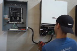
Assuming the PIP 3048LV-MK is the same, this is what it will look like in your set up.

1645335502473.png
Notice that when the inverter is on battery, the bonding relay creates an N-G bond. Since there should always be one, but only one N-G bond, the breaker box should keep the neutral and ground separate.

However, when the inverter is on AC-input (Pass-through) the Bonding relay removes the N-G bond. It is expecting the input to provide the bond.

Most small gasoline generators in the US do not provide an N-G bond so you have a few choices.
1) On some generators it is possible to open them up and connect the neutral and ground.
2) On generators that have multiple plugs on them, some people will plug this into an unused plug to create an N-G bond:
This works well, but you have to remember to use it.
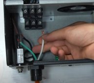
3) You can create a bond by putting a jumper between the AC input Neutral and Ground terminals. (THis can be a PITA because the terminals are typically not large enough for two full size wires.
4) You can make a 'pigtale' with an N-G bond. (This is essentially a short extension cord that has an N-G bond in one of the connectors. )
5) You can build an NG-bond into the extension cord between the generator and inverter.... but make sure not to use that cord elsewhere.

Note: If you are not familiar with the purpose and importance of the N-G bond, you may want to review these grounding tutorials:

 
Hmmmmmm... That is interesting.. My understanding is that the LV6548 has a Bonding relay so unless it is disabled when stacked for split phase, that set-up is ending up with 3 N-G bonds when on battery. Will does not often make mistakes so I may be missing something.

Maybe @Will Prowse can let us know if there is something special about the bonding relay when the inverters are stacked for split phase.

On the single inverter set-up you are planning, I am 99% sure that the inverter bonding relay will provide the N-G bond when powering from the battery. However, when in pass-through mode, the relay removes the N-G bond and the input needs to have the bond.
This is a good question.

The manual does not tell us much:
Screenshot_20220219-232705_Drive.jpgScreenshot_20220219-232746_Drive.jpg
The manual tells us that the neutrals need to be bonded (but does not say where). I also thought, what about case or ground terminal? Does the grounding terminal connect to neutral? I found out that the neutral and case ground are not connected in the unit.

So I asked watts 24/7 for the answer. I told Ian my problem, and shared that my loads required a N-G bond (Tesla charger).

He recommended to do a neutral ground bond at the panel.

I Thought about it for a few days, and other units that are similar. I did a similar bond on the input of the LV5048 a year ago (this configuration is actually in the manual). I realized that having a 12 gauge wire to bond at the terminals of the unit is not ideal. And I knew I needed the N-G bond for my Tesla charger. So I took Ian's advice and bonded neutrals and grounds at the panel. I prefer having a large conductor in case there is a overload. Having a small jumper wire could cause issues, and it looks pretty ugly.

I did not consider the bonding relay. I planned to run the system floating, and not connected to grid. If I had 240V input connected to grid, I would keep the neutrals and grounds separate. I really need to see a schematic or open it up to see how it's wired. I did place some trust in Ian because he has sold thousands of them and he can tell me information that is not present in the manual. I think the neutral ground bond works great in the panel because it's not a true Earth ground. It's a common bus for case connections really. This is a great spot to connect your server rack case ground if you have it. I consider it non current carrying, and ensures potential across cases is the same. Nothing more. If this system was tied to grid, I would design it a bit differently.
 
I would not consider it the "ground" as most people are used to. The ground on these units is the case, which should be non current carrying reference potential for the entire system. In marine systems, case/chassis are connected to a negative bus. Connected to the negative terminal of the battery. Considering these "all in ones" have pass through with grid, adding a bond can be problematic, as filterguy mentioned above. I think it really depends on how the system is configured, and what loads one plans to power.

I couldn't fit all 4 conductors in the neutral screw terminal on my panel. Because the ground is just for reference and to keep cases at same potential, I figured bonding anywhere to the bus is adequate.

If you want to make it look more tidy, you can keep two separate bars for neutral and grounds, and connect them at one point. I don't think it matters considering what the ground is used for in this instance. It just needs a solid connection. It is not earth ground, but you still should have a single bus for reference potential regardless.
 
Hi FilterGuy,
thank you for your fast response, my set up is completed off grid, only power using either solar panels or 48V batteries, it look pretty much like the screenshot attached with the MPP and a small sub-panel (not connected to house main panel), but I see Will bond N+G, that's why I was a bit confuse whether I need to bond or not
That's not the final wiring. And on that unit @FilterGuy there is not a N-G bond when used with the battery. I've had to do this on some other split phase models. The first time I ran into this problem was in my solar shed when charging my first Tesla.

Do you have a schematic or this ground neutral relay? I've been studying the victron relay configurations, and they are well thought out. But the MPP really depends on what model and what you plan to do with the unit
 
I'm also running a 6-50P that omits the use of neutral entirely, but the EV chargers I use do check if it is center tap neutral and if it's bonded (by the voltage of ground relative to the two hots). If it is not bonded, it does not work.

I am half awake but tomorrow I will probe the outputs and see what's going on. I'll figure it out.
 
Last edited:
These mpp units are well built and getting better as far as all around capabilities go, but the fact that this essential wiring process is guess work as far as the manual is concerned is not confidence inspiring when planning a system. Having a resource like Ian willing to help out would be the reason I'll keep purchasing from him.
So is the NG not bonded when wired split phase dual inverter only?
 
On an existing set-up,

The easiest way to check for the existence of an N-G bond is to check for voltage between neutral and ground. If there is little or no voltage, there is almost certainly an N-G bond someplace on the circuit. (It is best to do this when NOT under load) Since an inverter may dynamically create the NG bond, this should be tested when power is from the batteries and again when power is from the AC-IN.

The easy way to detect multiple N-G bonds is to look for current on the ground wire between the two possible N-G bonds while under load. If there are two N-G bonds, then the ground becomes a parallel conductor to the neutral and will carry ~ 1/2 the current.

1645375690330.png
 
The easiest way to check for the existence of an N-G bond is to check for voltage between neutral and ground. If there is little or no voltage, there is almost certainly an N-G bond someplace on the circuit.
I wouldn't have expected any voltage when there is no bond between ground and neutral regardless if there is a load or not. I would check for voltage first between ground and neutral. (If there is a significant difference, stop and think) If there isn't a voltage difference, check with the Ohm meter to see if there is a short circuit which could indicate either a deliberate or accidental (short circuit) connection?

Or am I missing something?
 
The Neutral-Ground bond serves TWO purposes:

1) It prevents the circuit from floating to some arbitrarily high voltage relative to the surrounding environment.
2) It provides a low impedance path that will clear a short between hot and ground.
 
I wouldn't have expected any voltage when there is no bond between ground and neutral regardless if there is a load or not.
When you have an inverter if there is no N-G bond you can almost guarantee there will be a significant voltage. The most common will be ~1/2 the rated output voltage of the inverter.... but I have seen other voltages as well. I have never dug into the reason for this but I suspect it is a natural outcome of inverter design.
 
There is continuity between both LV6548's neutrals and grounds whether the inverter is on or off. There is no setting for ground neutral relay in the manual. I also tried charging my tesla with the grounds disconnected, and it worked. Interesting.

I also tested voltage between the neutral and the ground, and there was potential only between one ground and the neutrals. It was 14VAC. 0V on the other ground.

I am thinking now that I should keep the grounds separated. Or should I? It is not a typical ground neutral bond and we have two supplies. So this is a tough one. What do you guys think?
 
Back
Top