OK.... Sorry. Is this the diagram?
View attachment 86057
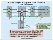
That one is confusing because the 'highlighted' current does not go through a load.
It is correct to say that there would be no objectionable current with a single 240 V load (or any perfectly balanced load).
However, with any imbalanced load there will be an objectionable current. (Unbalanced loads is the typical case if you have 120V loads)
The primary differences between the drawing I showed and the one above is that there is no Grid on the AC input and no xfer switch.
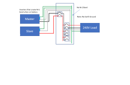
If we look at the same structure with an imbalanced load or just a single 120V load, we see that there is still an objectionable current path through the neutral of the Slave inverter onto the EGC circuit..
View attachment 86060
The purple dashed is the 'normal' current.
The Yellow Dashed is the 'objectionable' current.