diy solar

diy solar

Need to drain a 272ah lifepo4 battery cell

jofred99

New Member
Joined
May 4, 2020
Messages
9
I have a runner in my battery pack that keeps the rest of my cells from getting properly charged.

I like to put a resistor load on this cell to draw power on a temporary basis. The pack was top balanced prior to installation and only exhibited problems during an extended low light period within the last month.

What would the correct resistor(s) load to reduce capacity on a single cell in my battery bank?
 
Have you considered charging the other cells individually with your bench supply? This can be done without breaking the battery down.

The resistor will be guesswork, but taking all cells to 3.65V is exact.


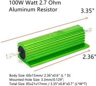
If you really want a resistor, you can decide for yourself:

How much current do you want? 3A?

R = V / I = 3.2 / 3 = 1.1Ω

P = I * V = 3 * 3.2 = 9.6W

A 1.1Ω resistor will bleed off 3A and will consume 9.6W of power, thus you'll want at least a 10W resistor, but higher is better.

Prefer 1A?

R = 3.2 / 1 = 3.2Ω

P = 1 * 3.2 = 3.2W

10A?

R = 3.2/10 = 0.32Ω

P = 10 * 3.2 = 32W

etc.

If you go this route, use fixed times, i.e., 3A will pull out 3Ah in an hour, so just connect it for a fixed time rather than watch voltages.
 
Currently using a 6 Volt Car Head Light to drain down my runners when needed. I just soldered wires to the High Beam Leads and put alligator clips on the end of the wires. Connect the alligator clips to the studs of the runner cell and it pulls down nicely. If I remember right it drains about 4 amps at approximately 3.6 volts.


The resistor sunshine_eggo lists should be less expensive.
 
I have a runner in my battery pack that keeps the rest of my cells from getting properly charged.

I like to put a resistor load on this cell to draw power on a temporary basis. The pack was top balanced prior to installation and only exhibited problems during an extended low light period within the last month.

What would the correct resistor(s) load to reduce capacity on a single cell in my battery bank?
I had a similar problem with one of my batteries.
I use a Hel-Tec active 5amp capacitive balancer.

Works great for me.

 
This is going to be a very popular question in the next few years.

Firstly with a good voltmeter, ensure that each cell reads exactly the same as what you are seeing on the BMS. That rules out a high resistance sense wire connection.

Adjust your charge source voltage until the battery is at “float”, but not triggering cell level high voltage disconnect.

Connect a resistor as shown above across the terminals of the highest cell and wait until it drops to the average cell value.

Then adjust the charge voltage up 0.1V at a time and repeat if required until you reach your target float voltage.
 
If the problem persists- i would replace the cell rather than fit an active balancer.

I try to minimise points of failure in my packs.
That’s true but not always feasible.
Especially if you buy the exact amount of cells..
 
Sure, also when cells are near end of life you can extend their life by using an active balancer. Obviously the main concern with a cell that is an obvious outlier is the chance it has dendrite damage and will fail completely causing a power outage.

What the OP has described is pretty common, more than likely once the cell is brought into line it will be fine. Definitely try what i said earlier before making any system changes.
 
Have you considered charging the other cells individually with your bench supply? This can be done without breaking the battery down.

The resistor will be guesswork, but taking all cells to 3.65V is exact.
I should have described my battery configuration. It has 2 272ah parallel cells and these are connected in 16 series connections for 48 volts.

I've tried to charge the individual cells, but while charging works, the other 14 cell are going lower and it is a never ending battle.

I had a similar problem with one of my batteries.
I use a Hel-Tec active 5amp capacitive balancer.

Works great for me.
I have an 3 amp active balancer on another 48v battery pack and do not have the same issues with runners. Good call and will look into acquiring another capacitive balancer.

This is going to be a very popular question in the next few years.

Firstly with a good voltmeter, ensure that each cell reads exactly the same as what you are seeing on the BMS. That rules out a high resistance sense wire connection.

Adjust your charge source voltage until the battery is at “float”, but not triggering cell level high voltage disconnect.

Connect a resistor as shown above across the terminals of the highest cell and wait until it drops to the average cell value.

Then adjust the charge voltage up 0.1V at a time and repeat if required until you reach your target float voltage.
Good call out on the BMS wire issue. I will check voltages today via my voltmeter.

I appreciate the input given and after a little over a year with my lifepo4 battery packs, I wonder if the charging manufacturers have a ways to go when building their products. All the charge controllers that I have seen assume that like FLA batteries, the individual cells have similar characteristics. Throw a charge current at the battery and all individual cells will respond in similar fashion. That was true with FLA batteries (except occasional equalization), but appears to fall short with the current lithium offering. BTW, my background is with solar charging for my home use.

What would happen if the individual cells that comprise a battery were charged according to their characteristics, instead of being charged as a whole? Maybe like charging individual cells via a CC/CV power supply, but powered by a solar array? For my 48v battery this would require 16 individual connections. Just my thoughts, but have not found a vendor that can supply this type of charger.
 
What would happen if the individual cells that comprise a battery were charged according to their characteristics, instead of being charged as a whole? Maybe like charging individual cells via a CC/CV power supply, but powered by a solar array? For my 48v battery this would require 16 individual connections. Just my thoughts, but have not found a vendor that can supply this type of charger.
this makes perfect sense in theory, it could selectively charge only cells that need it.

however it would likely result in a much more expensive charger due to need for N = number of cells number of chargers per pack instead of one
 
What you say regarding individual charging is correct, but would be expensive to implement.
For my packs, it is rare to use the full capacity - so the practice of setting the “float” voltage to a value the weakest cell can accept at the expense of a few % capacity is a workable solution.
Drain excess charge from your runner, set the float voltage a bit lower, and see how you go.
 
I had a similar problem with one of my batteries.
I use a Hel-Tec active 5amp capacitive balancer.

Works great for me.

Wondering which specific 5amp balancer worked great. Your link goes to many options. Do you have a web link to your specific favorite? and .. on LiFePO4 ? and What Ah ? ... Exploring options for a few below par ... 280Ah LiFePO4 Eve runner cells (peakers near full charge) :+)

Was it this one that worked great? https://heltec-bms.com/project/3s-21s-5a-capacitive-active-equalization-active-balancer/ ... I would choose the 6s-8s version for my 24v LiFePO4s set up.
 
Last edited:
Yes that balancer works fine. Get the 8S as you have 8 cells in series.

Balance current is still fairly small. Depending on the voltage spread between cells and the day to day charging voltage, battery may still over volt and take an extend period to improve balance. Best to reduce charging voltage to avoid triggering BMS protection.
 
Have you considered charging the other cells individually with your bench supply? This can be done without breaking the battery down.

The resistor will be guesswork, but taking all cells to 3.65V is exact.


If you really want a resistor, you can decide for yourself:

How much current do you want? 3A?

R = V / I = 3.2 / 3 = 1.1Ω

P = I * V = 3 * 3.2 = 9.6W

A 1.1Ω resistor will bleed off 3A and will consume 9.6W of power, thus you'll want at least a 10W resistor, but higher is better.

Prefer 1A?

R = 3.2 / 1 = 3.2Ω

P = 1 * 3.2 = 3.2W

10A?

R = 3.2/10 = 0.32Ω

P = 10 * 3.2 = 32W

etc.

If you go this route, use fixed times, i.e., 3A will pull out 3Ah in an hour, so just connect it for a fixed time rather than watch voltages.
I could really do with getting some of cells charged up.. I have a 10a bench supply with the intention of top balancing.. but with such a high deviation in my cells (0.2v) It's going to take too long. I hope this doesn't sound too dumb, but can I charge an individual cell with my power supply being powered from the inverter connected to the same battery pack? I really don't want to be running my big diesel geni for a 40w charge for multiple hours/days. Worst case I'll have to find and borrow a small inverter geni or something quiet and good on fuel, as I don't have any other source of power to plug the benchtop power supply into.
 
I could really do with getting some of cells charged up.. I have a 10a bench supply with the intention of top balancing.. but with such a high deviation in my cells (0.2v) It's going to take too long. I hope this doesn't sound too dumb, but can I charge an individual cell with my power supply being powered from the inverter connected to the same battery pack? I really don't want to be running my big diesel geni for a 40w charge for multiple hours/days. Worst case I'll have to find and borrow a small inverter geni or something quiet and good on fuel, as I don't have any other source of power to plug the benchtop power supply into.

I don't see why not, BUT I don't understand wiring well enough to say either way. The risk would be if somehow it could result in a short, but I believe there is sufficient isolation between the DC to AC inversion and then the AC to DC conversion. Since these are routinely used as "chargers" I'm confident that they have rectifiers or diodes that prevent backflow of the battery into the supply, so this would be additional isolation.

With the power supply disconnected from the cell and set to 3.65V, if you get 0V between each lead individually and each cell terminal individually, I'd personally choose to connect it. I think the worst case is you blow out the power supply.
Hey Bro, are you sure that was not you on the video "oh no... its a smoke..." :ROFLMAO::ROFLMAO::ROFLMAO:
 
I'd want to make sure that bench power supply was fully isolated or you run the risk of letting the smoke out of something.
 
Back
Top