rin67630
Solar Enthusiast
You have a gorgeous solar system and a battery bank to make Elon Musk jealous.
Well!
You can do better with your battery than feeding an inverter.
DC/DC is always more efficient than DC/AC/DC to carge a quantity of devices: your eBike, vacuum cleaner, computer, tablet and so on.
There are a lot of DC buck converters around, a few of them being boost/buck, that means they are able to convert voltage upwards and downwards.
These are really convenient to charge secondary batteries from your main battery at any voltage.
One of those digitally controlled boost/buck converter is the DPS3806 (38V/6A boost/buck converter) e.g.
https://www.aliexpress.com/item/1005001591485527.html

It is a nice well done and inexpensive module, but the digital control board is everything but convenient.
You have to fiddle with the tiny push buttons and the seven segment display is not really 21st-century.
Fortunately the digital control board is pluggable, and I was able to replace the unit with a powerful WiFi enabled ESP32 microcontroller.
The result is a fully WiFi networked DC-DC programmable power supply, with tons of features:

The power supply is controllable by:
All instructions to build and the corresponding program is available at GitHub:
Drok-Juntek on Steroids.
Enjoy!
Well!
You can do better with your battery than feeding an inverter.
DC/DC is always more efficient than DC/AC/DC to carge a quantity of devices: your eBike, vacuum cleaner, computer, tablet and so on.
There are a lot of DC buck converters around, a few of them being boost/buck, that means they are able to convert voltage upwards and downwards.
These are really convenient to charge secondary batteries from your main battery at any voltage.
One of those digitally controlled boost/buck converter is the DPS3806 (38V/6A boost/buck converter) e.g.
https://www.aliexpress.com/item/1005001591485527.html

It is a nice well done and inexpensive module, but the digital control board is everything but convenient.
You have to fiddle with the tiny push buttons and the seven segment display is not really 21st-century.
Fortunately the digital control board is pluggable, and I was able to replace the unit with a powerful WiFi enabled ESP32 microcontroller.
The result is a fully WiFi networked DC-DC programmable power supply, with tons of features:

The power supply is controllable by:
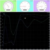
- USB -Serial with a simple menu to change the set-points control, the OLED display variants, the charging profiles and print reports.
- from everywhere in the world using the cloud dashboard service of https://thinger.io with a free limited maker account.
This is just an example, much more will come:

- a IR remote control.
- remote screen replication
- Energy report by the second, the minute, the hour.
- Ah, Wh Joule/Coulomb reports by the minutes, the hour, the day.
- Events of the charging process
- ...
Battery Charger mode:
- charging profiles for many battery chemistries
- evaluation of the battery's internal resistance
- evaluation of the battery' capacity
- charging time series plots
Power Source emulation:
- add a programmable internal resistance
- run a constant power mode
- emulation of solar panel / wind turbine incuding "pseudo-daily" gaussian cycles (accelerated 60x) to test solar chargers
Programmable Load
- together with a flooder to dissipate the energy, the buck-boost converter can be used to discharge batteries and transfer energy from one battery to another one.
Maybe other useful ideas that you might have...
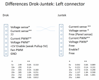
Last but not least everything is neatly self powered, and integrated on one single board, that plugs instead of the original controller board. If you wanted to revert to the original functionality, just replug the manufacturer's control board. There is absolutely no cable mess and even a new program can be updated over the air using a beginner's easy Arduino IDE. You need no additional computer to manage the dashboards, everything is done in the cloud. The only thing you need, is a Wifi connection.All instructions to build and the corresponding program is available at GitHub:
Drok-Juntek on Steroids.
Enjoy!
Last edited:


