Good to hear you got it up and running. Most of us use a resistor to charge up the capacitors in the system before closing the disconnect. I have a large 8 ohm resistor I normally use as a load for amplifier testing. I connect that across my disconnect switch, and it makes almost no spark, and in under 3 seconds, the inverter powers up to standby mode. Once I see the panel on the inverter is lit up, I know I can safely close the disconnect. At a maximum of 60 volts, even if the capacitors are completely discharged, the initial current is about 7.5 amps across the 8 ohm resistor. That is 450 watts for an instant, so use a decent sized resistor. Incandescent light bulbs also work great for this. A 60 watt bulb is 240 ohms once hot, but much lower when cold. That should charge up the capacitors in 10 seconds or so.
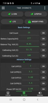
The Voltage and Current calibration values work a little odd. They are pre filled with the value it is currently measuring.
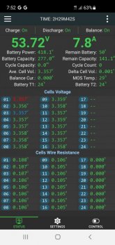
The voltage calibration is easy. Just measure the pack voltage at a light load and enter that value. When you select OK it will change the reading at the top of the status screen to the value you entered. It will scale the cell voltages off of that total voltage. I noticed mine would match my Fluke meter right after I did that, but it does drift a bit with temperature. It seems to hold within 1% if I measure at the same terminals on the battery bank where the balance lead wires are connected.
The current calibration is a bit trickier. You need to supply a very steady load of several amps. I can't use my Schneider inverter for this as the 60 Hz ripple current makes the reading jump around far too much. I put my 4 ohm test load across my battery bank output. At 55 volts, that pulls 13.75 amps and 756 watts. Yes, it gets quite hot pretty fast. My load is rated for 1,000 watts, but it was staring to glow a dull red. I measured the current with my Fluke and entered the value. And it adjusted the current and power display on the status screen to match.
So I got the readings from my BMS to closely match my Fluke meter. The current readings in the Schneider seem a little off, but the voltage is very close on the DC side. I have not found a way to calibrate the Schneider readings, but they are good enough. If I need perfect readings, I just use my Fluke. I trust it as it was nist calibrated by a Fluke dealer about 4 years ago. The Schneider readings are never off by more than 1% which is not too bad, but it is odd that it does not always agree with itself. In pass through mode it shows more power coming out than going in. If it was the other way around, I would say it is using some power internally, but in this case it is using negative power. The error is certainly not enough to be a problem. I just checked the battery voltage readings now. My garage is cold, just 55 F. The battery voltage at the terminals is 52.2 volts on both the Schneider and my Fluke meter, but the BMS is a tick high at 52.37 volts. That is just a 0.325 % error. When it get's over 70F in my garage, it will probably come back into to calibration. But I had done a reset when I had the balance wire issue, it may have erased my calibration changes. I will do another calibrate, but I'll wait until it gets a bit warmer.
I was just thinking, since it is charging at 27 amps right now, I would have expected the Schneider voltage reading to be a tick high due to wire resistance. It's true that 8 feet of 2/0 cable is not dropping much at 27 amps, but this is also going through the Anderson connector, 2 fuses, an Amazon disconnect switch, and the JK BMS. So measuring at the battery terminals, and internal to the Schneider XW-Pro both matching to 0.1 volt is pretty good. Doing the math, a 0.1 volt drop at 27 amps would require 0.0037 ohms of resistance. Maybe I will measure the actual drop and see how close I can get. My Fluke has a range where it can measure down to 0.1 mv up to 0.3 volts total.
Sorry, got rambling again.