I am brand-new here, so am unsure if I should include the details of my solar system (or if you'll just pull that from my profile info). MY QUESTION: On days when not at the cabin, and with no load on the system and consistently sunny days, the Renogy Rover Li 40 controller records via the Bluetooth app are consistently showing daily "Min Battery Volt" readings of 12.5 or 12.6 V. Do you have an idea as to what would be causing this? Does the controller do some sort of "cycling" of the batteries to assist in maintaining their performance? Thank you for your help! - Rick.


You are using an out of date browser. It may not display this or other websites correctly.
You should upgrade or use an alternative browser.
You should upgrade or use an alternative browser.
New 6 V battery bank charging fully each day but consistently going down to 12.5 or 12.6 V overnight with no load and no one at the cabin.
- Thread starter SkipSolar
- Start date
My System:
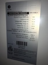
Solar Panels: 2X Heliene 300W 24V Monocrystalline (60M-300BLK)
Controller: Renogy Rover Li40 MPPT
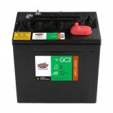
Battery Bank: Six Interstate 6 V GC2 Lead Acid Golf Cart batteries, wired in a series/parallel combination to produce 12 volts.
House voltage: 12 V (it's a Tiny Cabin with 12V LED light fixtures) We also have a 12V ceiling fan and a 100W inverter to run a TV (we disconnect the inverter when away from the cabin).
Solar Panels: 2X Heliene 300W 24V Monocrystalline (60M-300BLK)
Controller: Renogy Rover Li40 MPPT
Battery Bank: Six Interstate 6 V GC2 Lead Acid Golf Cart batteries, wired in a series/parallel combination to produce 12 volts.
House voltage: 12 V (it's a Tiny Cabin with 12V LED light fixtures) We also have a 12V ceiling fan and a 100W inverter to run a TV (we disconnect the inverter when away from the cabin).
Flooded lead batteries naturally drop to 12.5 ish volts with minimal load fairly quickly... if your setup is giving an alarm at 12.6V, then the settings are wrong.
Roger that. What would you suggest I set the controller parameters for a) low voltage cut-off for the load and b) low voltage alarm?Flooded lead batteries naturally drop to 12.5 ish volts with minimal load fairly quickly... if your setup is giving an alarm at 12.6V, then the settings are wrong.
a) 11.5
b) 11.6
Google says those are 225Ah batteries, so you have a 675Ah 12V battery bank.
600W of solar will provide 600W/12V = 50A of charging, but you're limited to 40A by your SCC.
Your optimal charge current is 67.5A. Charging at a lower rate encourages sulfation of the batteries causing capacity loss. This requires equalization charges to correct.
It sounds like your power requirements are very low, so I suspect that you're charged very quickly in the morning, so peak current doesn't matter If that's the case, then it's probably fine, but if you start increasing your utilization, you should consider adding additional solar to provide more charging current.
I don't see that Interstate offers much in the way of resources. I suggest you read and master the following resources:
 www.trojanbattery.com
b) 11.6
Google says those are 225Ah batteries, so you have a 675Ah 12V battery bank.
600W of solar will provide 600W/12V = 50A of charging, but you're limited to 40A by your SCC.
Your optimal charge current is 67.5A. Charging at a lower rate encourages sulfation of the batteries causing capacity loss. This requires equalization charges to correct.
It sounds like your power requirements are very low, so I suspect that you're charged very quickly in the morning, so peak current doesn't matter If that's the case, then it's probably fine, but if you start increasing your utilization, you should consider adding additional solar to provide more charging current.
I don't see that Interstate offers much in the way of resources. I suggest you read and master the following resources:
Trojan Battery | Battery Maintenance
The key to achieving optimum performance and long battery life is to follow a regular care and maintenance program. Read our tips for high performance battery maintenance.
www.trojanbattery.com
a) 11.5
b) 11.6
Google says those are 225Ah batteries, so you have a 675Ah 12V battery bank.
600W of solar will provide 600W/12V = 50A of charging, but you're limited to 40A by your SCC.
Your optimal charge current is 67.5A. Charging at a lower rate encourages sulfation of the batteries causing capacity loss. This requires equalization charges to correct.
It sounds like your power requirements are very low, so I suspect that you're charged very quickly in the morning, so peak current doesn't matter If that's the case, then it's probably fine, but if you start increasing your utilization, you should consider adding additional solar to provide more charging current.
I don't see that Interstate offers much in the way of resources. I suggest you read and master the following resources:
Trojan Battery | Battery Maintenance
The key to achieving optimum performance and long battery life is to follow a regular care and maintenance program. Read our tips for high performance battery maintenance.
Thanks for all the info and resource links, snoobler! Very much appreciated! A few additional clarifications on my system:
My solar panels are actually 300W/24V each, so 600W/24V coming into the controller. Each panel can do a max of 9.13 max amps at load, so 18.26 for the pair (at 24V). With the converter converting to 12V (2X the amps) my understanding is that the solar array max possible production would be 36.52 amps. Also, I believe that my batteries are 210Ah each, so a total of 630Ah for the 12V the bank.
I'm still relatively new to all of this, so I realize I may not have all my details right. Therefore, I have attached 2 image files for reference: 1) the sticker on the back of the solar panels, and 2) the sticker on my particular batteries.
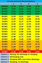
I just located a "State of Charge" chart that I've been studying (see attached image file). No source is listed, so I'm a bit hesitant to use it. Do you have something similar from a recognized source that you could share with me?
Thanks again!
Attachments
I'm now digging into the topic of surface charge re: lead acid batteries, including normalizing the condition via switching on a load to remove 1% of the battery's capacity prior to testing, etc. I'll be out at the cabin this weekend, and will be doing some testing. In particular, I want to see how the battery bank voltage comes back after I take the load off.
Thanks for everyone's patience re: my learning curve!
Thanks for everyone's patience re: my learning curve!
A controller's current rating is for output, i.e., a 40A controller will output 40A max to the batteries. Assuming MPPT controller, the input voltage and current doesn't matter provided they meet the controller's input limits, so 600W/12V = 50A is the relevant number. Your controller can't handle the existing panel power at peak.
Unfortunately, I can't see any details on the battery. Hopefully, it lists the float and bulk/absorp voltages, and you have your controller properly set to that.
The chart is typical. The unique in my experience that it lists charge and discharge parameters. If those discharges are for a C20 rate and charge for C10, then it's a reasonable resource. The charge is in question as it peaks at 13.8 when most FLA need to go to 14.X to achieve full charge. 13.8 is typical of AGM UPS type installations where the batteries are held in a state of high float for very long periods of time and only discharge infrequently.
The resting voltage column is consistent with other resources. The kicker is resting is RESTING... no current in or out for MANY hours. 10 at a minimum and 24 hours for best results.
FLA/AGM charging works as follows:
0.1C (in your case 67.5A) input to 14.4-14.8V (bulk phase)
Hold 14.4-14.8V by decreasing current as the battery fills (absorption phase)
Once current drops to 2% of C (.02 * 675 = 13.5A), battery is full.
Terminate charging and supply only enough current to maintain the float voltage, 13.2-13.8V typical.
Once the controller can't maintain float, the battery voltage will drop into the 12.6-12.9 range when left to sit.
Surface charge with FLA/AGM isn't a bad thing. It further discourages sulfation of the plates. Bleeding off 1% may be useful in estimating state of charge, but there are better ways.
Will lists a battery monitors on his website:
You program these with your battery's (not all include all items):
capacity
fully charged voltage
tail current (the 2% termination current above)
Peukert effect (how the change in current affects the change in a battery's capacity)
charge efficiency
The monitor resets itself with every full charge. Then it COUNTS the Ah used and compares it to the programmed capacity, 675Ah in your case. It then reports a % state of charge (SoC).
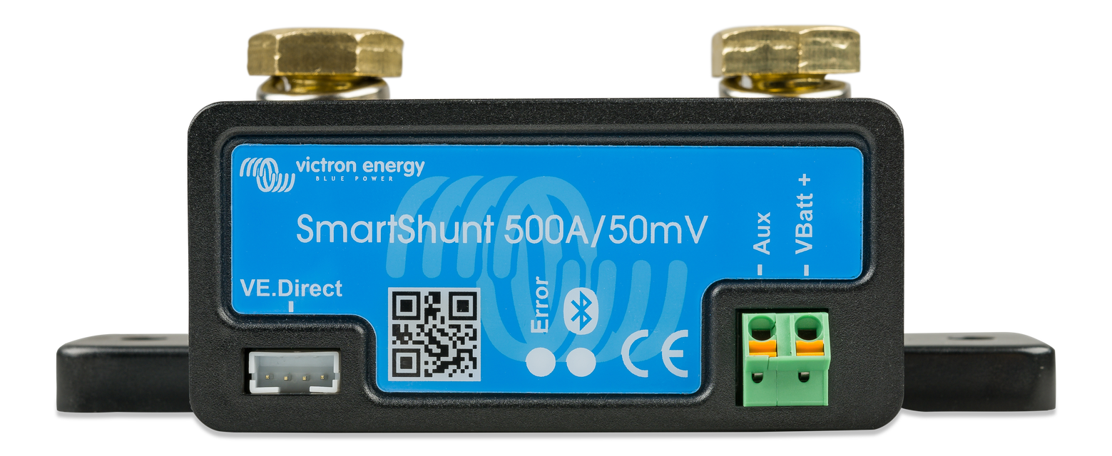
Any of those units should give a good approximation of SoC. However, the more expensive Victron BMV units include all of the parameters I listed and provides a very accurate SoC calculation.
The key in selecting any battery monitor is to ensure the shunt or hall effect sensor meets your current requirements according to the following formula:
peak Load (watts) / system voltage / 0.66
example:
2000W / 12V / 0.66 = 252A
A 2000W inverter on a 12V system would require a 252A minimum shunt. The 0.66 is a safety factor to ensure you're not running the shunt at its limit. The 0.66 does not apply to a hall effect sensor where you have a sensor around the cable to measure current.
In all cases a little bigger doesn't hurt. A 350 or 500A shunt would be fine for this example. 1000A would be a little much as the current sensing becomes less accurate.
If you're looking to throw a bit of money at the problem and get a reasonably accurate SoC, then a battery monitor is for you.
Lastly, FLA/AGM batteries require temperature compensated charge unless they're in a 77°F controlled environment. Hopefully, your charge controller has a provision for a temperature sensor.
Unfortunately, I can't see any details on the battery. Hopefully, it lists the float and bulk/absorp voltages, and you have your controller properly set to that.
The chart is typical. The unique in my experience that it lists charge and discharge parameters. If those discharges are for a C20 rate and charge for C10, then it's a reasonable resource. The charge is in question as it peaks at 13.8 when most FLA need to go to 14.X to achieve full charge. 13.8 is typical of AGM UPS type installations where the batteries are held in a state of high float for very long periods of time and only discharge infrequently.
The resting voltage column is consistent with other resources. The kicker is resting is RESTING... no current in or out for MANY hours. 10 at a minimum and 24 hours for best results.
FLA/AGM charging works as follows:
0.1C (in your case 67.5A) input to 14.4-14.8V (bulk phase)
Hold 14.4-14.8V by decreasing current as the battery fills (absorption phase)
Once current drops to 2% of C (.02 * 675 = 13.5A), battery is full.
Terminate charging and supply only enough current to maintain the float voltage, 13.2-13.8V typical.
Once the controller can't maintain float, the battery voltage will drop into the 12.6-12.9 range when left to sit.
Surface charge with FLA/AGM isn't a bad thing. It further discourages sulfation of the plates. Bleeding off 1% may be useful in estimating state of charge, but there are better ways.
Will lists a battery monitors on his website:
Off-grid Solar Battery Monitors
Building a vehicle mounted solar power system? Let me help.
www.mobile-solarpower.com
You program these with your battery's (not all include all items):
capacity
fully charged voltage
tail current (the 2% termination current above)
Peukert effect (how the change in current affects the change in a battery's capacity)
charge efficiency
The monitor resets itself with every full charge. Then it COUNTS the Ah used and compares it to the programmed capacity, 675Ah in your case. It then reports a % state of charge (SoC).
Any of those units should give a good approximation of SoC. However, the more expensive Victron BMV units include all of the parameters I listed and provides a very accurate SoC calculation.
The key in selecting any battery monitor is to ensure the shunt or hall effect sensor meets your current requirements according to the following formula:
peak Load (watts) / system voltage / 0.66
example:
2000W / 12V / 0.66 = 252A
A 2000W inverter on a 12V system would require a 252A minimum shunt. The 0.66 is a safety factor to ensure you're not running the shunt at its limit. The 0.66 does not apply to a hall effect sensor where you have a sensor around the cable to measure current.
In all cases a little bigger doesn't hurt. A 350 or 500A shunt would be fine for this example. 1000A would be a little much as the current sensing becomes less accurate.
If you're looking to throw a bit of money at the problem and get a reasonably accurate SoC, then a battery monitor is for you.
Lastly, FLA/AGM batteries require temperature compensated charge unless they're in a 77°F controlled environment. Hopefully, your charge controller has a provision for a temperature sensor.
Much of what you're telling me is way over my head at this point, but here's what I can answer:
Yes on the controller being MPPT: Renogy Rover Li 40

 www.renogy.com
- Automatically detects 12V or 24V DC system voltages. Compatible with various Deep Cycle battery options: Sealed, Gel, Flooded, and Lithium.
www.renogy.com
- Automatically detects 12V or 24V DC system voltages. Compatible with various Deep Cycle battery options: Sealed, Gel, Flooded, and Lithium.
- Innovative MPPT technology with high tracking efficiency up to 99% and peak conversion efficiency of 98%.
- Electronic protection against reverse polarity, overcharging, over-discharging, overload, short-circuiting, and reverse current.
- LCD screen and multiple LED indicators for displaying system operation information, customizable parameters, and error codes.
- Features diverse load control; also capable of charging over-discharged lithium batteries.
- It has default settings for FLA batteries, which can be modified.
- Four charging stages: Bulk charge, constant charging, boost charge, Float charge (and I do have the optional remote temperature sensor re: temp compensated charging)
- Auto equalization is carried-out every 28 days
This controller shows readings for:
- Solar panel voltage
- Charging current
- Battery voltage
- Battery %
- Load current
- Accumulated Ah
- Discharged Ah
QUESTION: With the read-outs that I have available from this controller, would a battery monitor still be needed/useful?
RE: Your controller can't handle the existing panel power at peak.
I consulted first with Renogy tech support before buying this controller to go with my specific pair of solar panels. They confirmed that the controller could handle the two 300W/24V panels that I purchased due to the 24V to 12V conversion, which is handled automatically by the controller.
The only specs I have on my batteries are:
6V
105 RC @ 75A
210 Ah @ 20hr
Yes on the controller being MPPT: Renogy Rover Li 40
Rover Li 40 Amp MPPT Solar Charge Controller
Buy Renogy's Rover 40 Amp MPPT Solar Charge Controller. Pair it with our BT-1 the BT app through bluetooth and you can monitor and adjust your solar system directly from your phone. Our Rover also comes covered in a die-cast aluminum exterior. This allows for safe heat dissipation along with...
www.renogy.com
- Innovative MPPT technology with high tracking efficiency up to 99% and peak conversion efficiency of 98%.
- Electronic protection against reverse polarity, overcharging, over-discharging, overload, short-circuiting, and reverse current.
- LCD screen and multiple LED indicators for displaying system operation information, customizable parameters, and error codes.
- Features diverse load control; also capable of charging over-discharged lithium batteries.
- It has default settings for FLA batteries, which can be modified.
- Four charging stages: Bulk charge, constant charging, boost charge, Float charge (and I do have the optional remote temperature sensor re: temp compensated charging)
- Auto equalization is carried-out every 28 days
This controller shows readings for:
- Solar panel voltage
- Charging current
- Battery voltage
- Battery %
- Load current
- Accumulated Ah
- Discharged Ah
QUESTION: With the read-outs that I have available from this controller, would a battery monitor still be needed/useful?
RE: Your controller can't handle the existing panel power at peak.
I consulted first with Renogy tech support before buying this controller to go with my specific pair of solar panels. They confirmed that the controller could handle the two 300W/24V panels that I purchased due to the 24V to 12V conversion, which is handled automatically by the controller.
The only specs I have on my batteries are:
6V
105 RC @ 75A
210 Ah @ 20hr
Renogy tech support barely know their products let alone have the ability to translate it to customer needs. Even if they did know what they were talking about, they likely didn't have the ability to educate you effectively.
The ONLY current that matters in this discussion is the CURRENT TO THE BATTERY. The Renogy controller is limited to 40A to the battery.

40A * 12V = 480W.
As the battery approaches full, it can handle 40A * 14V = 560W
So your controller can't utilize the full 600W of your panels.
The MPPT is a sophisticated DC-DC converter that takes high voltage, low current PV input and outputs up to 40A of current to a 12 or 24V battery.
They LIKELY meant that on a 24V BATTERY, the controller could handle your panels, but couldn't say it in a way you could understand. 12, 24, 36, 48, 96V panels have no meaning here.
You could put panels in series up to the 50A/100V limit on your controller, and you'd be in the same boat. You could conceivably put 50A * 100V or 5000W or panels on your controller, but it could only use 40 * 12 = 480W.
From:

There's clearly a 520W limit meaning it can't deliver the full 40A as the battery fills.
I hope that's clear.
The % on the Renogy is purely voltage based and is a GROSS approximation of your battery's SoC.
If you want to know your actual SoC, you need a battery monitor.
The ONLY current that matters in this discussion is the CURRENT TO THE BATTERY. The Renogy controller is limited to 40A to the battery.
40A * 12V = 480W.
As the battery approaches full, it can handle 40A * 14V = 560W
So your controller can't utilize the full 600W of your panels.
The MPPT is a sophisticated DC-DC converter that takes high voltage, low current PV input and outputs up to 40A of current to a 12 or 24V battery.
They LIKELY meant that on a 24V BATTERY, the controller could handle your panels, but couldn't say it in a way you could understand. 12, 24, 36, 48, 96V panels have no meaning here.
You could put panels in series up to the 50A/100V limit on your controller, and you'd be in the same boat. You could conceivably put 50A * 100V or 5000W or panels on your controller, but it could only use 40 * 12 = 480W.
From:
There's clearly a 520W limit meaning it can't deliver the full 40A as the battery fills.
I hope that's clear.
The % on the Renogy is purely voltage based and is a GROSS approximation of your battery's SoC.
If you want to know your actual SoC, you need a battery monitor.
That makes sense re: the need for a battery monitor to measure my actual state of charge.
I have certainly experienced some "hit and miss" with Renogy tech support. Please help me understand the "Max Input Solar Power" second line which shows "24V @ 1040W". Am I understanding correctly that this is based on the controller being connected to a 24V battery bank? (vs. a solar panel rated as a 24V panel)
And if I've completely frustrated you at this point, I won't take it personally if you prefer not to follow-up with me further. I do appreciate your help, though.
LOL... not frustrated at all. You finally got it. ")
The charge controller can deliver only 40A to the battery, either 12V or 24V. Power in Watts is Voltage * Current.
The 12V/24V on that line are in reference to the battery voltage, not the panels.
The charge controller can deliver only 40A to the battery, either 12V or 24V. Power in Watts is Voltage * Current.
The 12V/24V on that line are in reference to the battery voltage, not the panels.