


You are using an out of date browser. It may not display this or other websites correctly.
You should upgrade or use an alternative browser.
You should upgrade or use an alternative browser.
New Daly "Smart" BMS w/ Communication. (80-250A)
- Thread starter Will Prowse
- Start date
ultrakiev
New Member
- Joined
- Feb 25, 2021
- Messages
- 95
I agree it should be dowgraded.Using a Daly 200A smart bms I have drawn 180 A for 5 minutes. As with most bms systems the output wires are undersized for the rated current. In this case they started to warm up. My suggestion is to derate the “marketed” capacity by 50%
But the wires they are using is smaller gauge but silicon insulation 200C so it should handle the 100% duty load without melting anything.
I would use it only with proper design with good ventilation or cooling in place and BMS mounted with heatsink away from batteries if I want to run 100% duty cycle . limited use I guess at 100% load.
I'm building battery with 60A BMS and max I will be using 40Amp draw maybe occasionally 50A.
50% capacity it's a good rule of thumb but if considering price point 20-30% would be my choice.
Varney1241
New Member
- Joined
- Jun 17, 2020
- Messages
- 30
I had a Hall effect device and a shunt hooked up in early testing and all three were fairly close in value. For the SOC meter i cant say. When first used the BMS, the SOC meter was way off on one of the BMSs 75% vs 100% (i am building two packs) with similar battery voltages. Contacting Daly I asked how to calibrate the SOC. Daly said to set the battery capacity (AH)Did you test how accurate SOC and amps readings?
and then charge the battery to the high cell cut off protection value. To make things easy i just lowered the cell protection value to the existing voltage and the BMS turned off the charge Mos as expected. After Increasing the cell protection value and Rebooted the BMS the SOC then showed 100%. Accuracy is unknown.
Varney1241
New Member
- Joined
- Jun 17, 2020
- Messages
- 30
I also agree, the batteries packs I am building are for my RV and you can see will not ventilated. Very much heat here would be a problem.I agree it should be dowgraded.
But the wires they are using is smaller gauge but silicon insulation 200C so it should handle the 100% duty load without melting anything.
I would use it only with proper design with good ventilation or cooling in place and BMS mounted with heatsink away from batteries if I want to run 100% duty cycle . limited use I guess at 100% load.
I'm building battery with 60A BMS and max I will be using 40Amp draw maybe occasionally 50A.
50% capacity it's a good rule of thumb but if considering price point 20-30% would be my choice.
Attachments
ultrakiev
New Member
- Joined
- Feb 25, 2021
- Messages
- 95
In case like this it definitely should by 50%. Unless you want to install temp regulated fan. I believe you can set you bms to high T cutout as well for extra safety. Somewhere at 45C and play with load to see how far you can push your amps before it triggers T cutout. Then you will know you duty cycle.
ultrakiev
New Member
- Joined
- Feb 25, 2021
- Messages
- 95
What kind of case brand it is?
I also agree, the batteries packs I am building are for my RV and you can see will not ventilated. Very much heat here would be a problem.
Varney1241
New Member
- Joined
- Jun 17, 2020
- Messages
- 30
In case like this it definitely should by 50
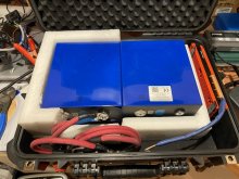
well i ran a fairly large load using the packs in parallel for 30 mins. Everything stayed cool to the touch. Just need this thing to brew me a pot of coffee in the mornings at parks where generators are not allowed.In case like this it definitely should by 50%. Unless you want to install temp regulated fan. I believe you can set you bms to high T cutout as well for extra safety. Somewhere at 45C and play with load to see how far you can push your amps before it triggers T cutout. Then you will know you duty cycle.
Attachments
Varney1241
New Member
- Joined
- Jun 17, 2020
- Messages
- 30
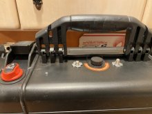
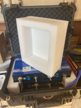
Its from Harbor Freight. Everything fit very well.What kind of case brand it is?
I padding around the batteries is repurposed shipping materials
Attachments
ultrakiev
New Member
- Joined
- Feb 25, 2021
- Messages
- 95
I will make my with 3D printed elements to hold batteries together and I will use industrial velcro to attach it to a case. I have unit I build with SLA battery 18A holds really good. ( Its portable bank/solar generator ) . Unfortunately we don't have the Harbor Freight in Canada. It's nice store.
My battery bank is not arrived yet. I will post some pictures later in April probably.
Here in PDF sketch for my future bank. All elements should fit in a Pelican case.
My battery bank is not arrived yet. I will post some pictures later in April probably.
Here in PDF sketch for my future bank. All elements should fit in a Pelican case.
Attachments
Last edited:
Proper electrical design should always leave margin between the use case and the limits of the equipment. Probably not 50%, but a 20% derating is pretty common to ensure that problems do not evolve from pushing the limits.In case like this it definitely should by 50%. Unless you want to install temp regulated fan. I believe you can set you bms to high T cutout as well for extra safety. Somewhere at 45C and play with load to see how far you can push your amps before it triggers T cutout. Then you will know you duty cycle.
The temperature rise needs to be taken into consideration. A lot of people quote the max current in a system before the wire insulation is compromised. You don't want to be anywhere near that limit, especially in a mobile installation.
John Frum
Tell me your problems
- Joined
- Nov 30, 2019
- Messages
- 15,233
There is normal de-rating as an engineering best practice and then there is de-rating for "Ebay" optimism to rhyme with fraud.Proper electrical design should always leave margin between the use case and the limits of the equipment. Probably not 50%, but a 20% derating is pretty common to ensure that problems do not evolve from pushing the limits.
The temperature rise needs to be taken into consideration. A lot of people quote the max current in a system before the wire insulation is compromised. You don't want to be anywhere near that limit, especially in a mobile installation.
Regarding the communications on these BMSes, I read the UART / RS-485 / CAN docs and I don't see any provision to change the addresses of individual BMS modules so that they can share a common communication bus, which is usually the point of RS-485 or CAN. Is there some undocumented way to do this or perhaps some jumpers or resistors inside to change the device addresses? I'm trying to run opto-isolated UART / RS-485 / CAN with 8 48V (15s) BMSes in a series configuration.
CoachLife
New Member
- Joined
- Jan 14, 2021
- Messages
- 36
That's why I bought the 500amp for a 200 amp load.Using a Daly 200A smart bms I have drawn 180 A for 5 minutes. As with most bms systems the output wires are undersized for the rated current. In this case they started to warm up. My suggestion is to derate the “marketed” capacity by 50%
Varney1241
New Member
- Joined
- Jun 17, 2020
- Messages
- 30
Maybe order online from HFI will make my with 3D printed elements to hold batteries together and I will use industrial velcro to attach it to a case. I have unit I build with SLA battery 18A holds really good. ( Its portable bank/solar generator ) . Unfortunately we don't have the Harbor Freight in Canada. It's nice store.
My battery bank is not arrived yet. I will post some pictures later in April probably.
Here in PDF sketch for my future bank. All elements should fit in a Pelican case.
Attachments

Varney1241
New Member
- Joined
- Jun 17, 2020
- Messages
- 30
Yes for sure, the temperature probe is displayed on the app so it ahould be easy to monitor.Proper electrical design should always leave margin between the use case and the limits of the equipment. Probably not 50%, but a 20% derating is pretty common to ensure that problems do not evolve from pushing the limits.
The temperature rise needs to be taken into consideration. A lot of people quote the max current in a system before the wire insulation is compromised. You don't want to be anywhere near that limit, especially in a mobile installation.
My project is to build four Lishen 300Ah 12Volt LiFePos, each with its own Daly Smart BMS. I want to connect them in parallel. In doing so, it seems better to me to connect a system of four batteries in parallel because of redundancy, rather than simply building a large 12,000 Ah battery with one BMS. If there should be problems with one cell, then not the whole electrical system would fail, but only one of the four batteries. And the others would continue to do the job.
I am a layman, so I have a question: I noticed that all BMS for individual batteries, as they are also installed in the "drop in" batteries, Daly etc, switch the negative. As far as I know you would have to switch and fuse in the positive side, since minus is at ground (Europe). Does anyone know why the BMS switch minus, and how does that work in a (in my case two-pole but) grounded electrical system?
I am a layman, so I have a question: I noticed that all BMS for individual batteries, as they are also installed in the "drop in" batteries, Daly etc, switch the negative. As far as I know you would have to switch and fuse in the positive side, since minus is at ground (Europe). Does anyone know why the BMS switch minus, and how does that work in a (in my case two-pole but) grounded electrical system?
Last edited:
Using PC PCMaster.exe, you can view and change the address (originally 210).Regarding the communications on these BMSes, I read the UART / RS-485 / CAN docs and I don't see any provision to change the addresses of individual BMS modules so that they can share a common communication bus, which is usually the point of RS-485 or CAN. Is there some undocumented way to do this or perhaps some jumpers or resistors inside to change the device addresses? I'm trying to run opto-isolated UART / RS-485 / CAN with 8 48V (15s) BMSes in a series configuration.
However, my issue (see my post above) is that I am not able to make RS-485 Modbus communication working at all.
I did and I shared my experiences in a separated thread:Did you test how accurate SOC and amps readings?

Daly BMS - Large Discharge Current Reading Errors
I am testing/trying the settings of my new Daly 4s 250A smart BMS. So far, I found that all those end/over/under voltage protection settings work. However, I found that the errors in the discharge current reading in the PC App (Sinwealth) are large. - No discharge current is displaced (when...
 diysolarforum.com
As no one replies to to my thread yet...so I am not sure whether it is only a problem of my BMS or in general, amp readings of Daly BMS is really around 10% as per the last message I got from Daly support.
OK, the mystery solved thanks to KaFun: RS-485 is here, but not Modbus, there runs the same "UART" protocol as throught UART connector.Using PC PCMaster.exe, you can view and change the address (originally 210).
However, my issue (see my post above) is that I am not able to make RS-485 Modbus communication working at all.
Hi, just saw this post, regarding those 3pins in the middle on your picture, mine is exactly like that, and i connect the usb cable from the package to that port to program the BMS with PC! so i doubt it has anything to do with relay, because it works with both Daly PC apps, simultaneously with BT being connected to the other side. Mine is R05A-GC18 (4S 12V 100A) and the 3pin is labeled monitor.There is a useful document On the Daly website here which lists the pinout for the Multi pin connectors around the BMS board. Using google translate it’s possible to understand parts of the Chinese text, and the one which jumped out is the two pin J5 connector, shown in the below images.
The text in the table translates as “short pin 1 and pin 2 to activate BMS”.
I’ve tried this and it’s working on my 4S 80A unit, but it seems the short needs to be applied around 2 seconds as a brief momentary short doesn’t do the trick. I don’t know if applying a permanent short to these pins would keep the BMS active indefinitely, and I’m a little wary of trying this in case it could cause damage. If anyone who is trying to disable the sleep function on the BMS is brave enough to do this, let me know how it goes!
The 3 pin connector on my 4S BMS next to J5 seems to line up with the RLY pins on P1 in the wiring chart (to drive external relays?) and the other two pin connector (on the left in my photo) seems to align with VCC_ex and GND_ex in P1 (taking into account the spacing which misses a pin in P1). Would this be external power to drive an off board device? There‘s around 3V present on these pins when I meter them.
I’ve now fitted a momentary action push button switch on a short cable, wired into this J5 connector via a cut down RC model servo lead connector (cut down from 3 pins to 2 pins it will fit ok). Now I can press a button to wake the BMS when I want to connect via Bluetooth. Having the Bluetooth connection go back to sleep after the default 3600 seconds (one hour) is fine, as it will save battery power. If J5 can be held closed without causing any problems, then it would be possible to use a toggle switch and set the “sleep timer” via the mobile app to a very low number of seconds. Then you would have a two position switch for BMS on/off (presumably the off only works when the SCC is not charging the battery, as the charging will keep the BMS awake even with switch in off position).
View attachment 26937
View attachment 26936
View attachment 26935
Last edited:
Similar threads
- Replies
- 7
- Views
- 1K
- Replies
- 25
- Views
- 3K
- Replies
- 251
- Views
- 21K
- Replies
- 16
- Views
- 3K