


You are using an out of date browser. It may not display this or other websites correctly.
You should upgrade or use an alternative browser.
You should upgrade or use an alternative browser.
New Drawing - Please Advise
- Thread starter LSC
- Start date
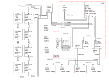
Anybody think this is done correctly. I read Will's book front to back and did all the calculations based on his examples. I will be running a few 10W LED bulbs for lights, CPAP's and our fridge.
LED Lights 10W x 5 = 50w x 5 hrs = 250 wh
CPAP (2) = 180 W x 8 hrs = 1440 wh
Fridge = 720W x 4 hrs (compressor on time in 24 hrs) = 2880 wh
Total = 4570 wh
I figure the system can produce 4800 wh. Will this system above work? What is not clear is will the solar panels have enough power to recharge the batteries the next day? Not sure how to figure this one. Thanks for any help.
BentleyJ
Solar Wizard
Solar panel output is roughly estimated by taking the STC rating of the panels (100W x 8 =800W) and multiplying by 5 solar hours per day on average. That would put your system at about 4.000 watts per day which varies by season and panel orientation. There are a number of calculators online that will estimate solar output by zip code, azimuth and tilt.
Some comments on your drawing:
Unless you plan to add a 3rd (or more) string of solar panels then you do not need a combiner box or any fuses. Your 2 strings are less than 12A total and with 2 strings no fusing is needed. Your charge controller should be able to support twice the amount of solar you have planned so you have lots of room to grow.
You have a 3000W inverter on a 24V system. That means you could pull up to 3000W / 24V / 85% efficiency = 150A from the batteries. 4AWG is way too small to support that kind of load. You should be using at least 1AWG. 1/0AWG would be better, especially if you plan on having loads near 3000W on occasion.
There's no need for 2 breakers between the batteries and inverter. And 80A is way too small for your inverter. Instead, you should have a 200A Class T fuse between the battery positive and the positive bus bar. But only use a 200A fuse if you properly upgrade your wire to 1AWG or 1/0AWG.
WindWizard
Solar Enthusiast
I don't think I would go 4p on the panels. That is getting too close to 100 volts. The 12 gauge panel wire seems a bit light. I would go at least 10 awg. for the solar panels. Probably 3S3P would be nice for the panels.
Some comments on your numbers:
Your daily usage is 4570Wh assuming you only have those three loads.
Your batteries are 4 x 12.8V x 100Ah = 5120Wh x 90% usable = 4608Wh usable. So your batteries are barely enough to last one day. Considering the need to run a CPAP you really want more capacity to be safe.
Your 800W of panels might produce 700W on a good day. If you get 5 hours of solar then that's only 3500Wh. You might get more in the summer. You will get much less in the winter or cloudy days. So even on a really good day you won't get enough solar to replace the 4570Wh needed each day. You either need more solar or you will have to plug in your all-in-one to recharge the batteries some of the time.
I assume you mean 4S. 4P would only be 20.23V.I don't think I would go 4p on the panels. That is getting too close to 100 volts. The 12 gauge panel wire seems a bit light. I would go at least 10 awg. for the solar panels. Probably 3S3P would be nice for the panels.
Based on a typical temperature coefficient of -0.3%/ºC for many solar panels, those 4 panels in series would need to get down to about -64ºF/-53ºC to reach 100V. I see no issue with those panels in 4S on a 100V SCC unless the OP lives in a seriously cold place.
12AWG wire to the combiner should be fine. Each string is 80V at under 6A.
One more comment on your drawing:
To the right of the solar panels you have 3 different arrangements with the voltage, amperage, and wattage. None of the wattage numbers are correct. 4S2P would be 800W since it is 8 100W panels. 3S3P is 900W (9 100W panels), and 4S3P is 1200W (12 100W panels).
The mistake you made is multiplying the Voc times the current. A panel's wattage is its Vmp x Imp. Voc is not used in calculating the panel wattage. And it's unclear which amperage value you used (Isc or Imp).
Use Voc when working out the panel voltage to ensure it's below the max PV input voltage of the charge controller. But remember that Voc goes up as the temperature goes below STC (25ºC/77ºF).
I will put 2 additional batteries in series and then in parallel with the others.Your batteries are 4 x 12.8V x 100Ah = 5120Wh x 90% usable = 4608Wh usable. So your batteries are barely enough to last one day. Considering the need to run a CPAP you really want more capacity to be safe.
That results in 6 x 12.8 x 100Ah = 7680Wh x 90% = 6912Wh which is 2342Wh more than calculated. This should work.
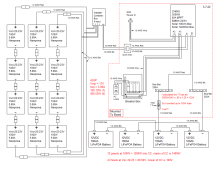
Here is a revised diagram with the changes. Did I get close this time. There are notes in red per your replies.
Attachments
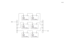
Why not use 3 24V 100Ah batteries instead of 6 12V 100Ah batteries? Avoid the possible issues of having batteries in series. You need a better way to wire the batteries in parallel. You do not want the main positive and negative (to the bus bars) coming off the same series pair. See chapter 3 of Victron's "Wiring Unlimited" book.

 diysolarforum.com
The 4S3P solar array would be 1200W with a combined Vmp of 68V and Imp of 17.67A.
With 3 solar panel strings in parallel you need to fuse each string. Perhaps your combiner box supports the use of breakers.
Why use 12 100W panels? Why not use 3 400W panels or 4 300W panels or even 6 200W panels?
Your calculation of the Class T fuse size is incorrect. You need to divide by the 85% inefficiency, not multiply.
3000W / 24V / 85% = 150A. That's for choosing the wire size. The fuse size is then 125% times that value. 150A x 1.25 = 187.5A which means a 200A fuse.
Wiring Unlimited
Wiring Unlimited is a great resource that covers many many common topics and questions relevant to DIYers. It is a free E-book from Victron Written by Margreet Leeftink. Check it out! Download
diysolarforum.com
The 4S3P solar array would be 1200W with a combined Vmp of 68V and Imp of 17.67A.
With 3 solar panel strings in parallel you need to fuse each string. Perhaps your combiner box supports the use of breakers.
Why use 12 100W panels? Why not use 3 400W panels or 4 300W panels or even 6 200W panels?
Your calculation of the Class T fuse size is incorrect. You need to divide by the 85% inefficiency, not multiply.
3000W / 24V / 85% = 150A. That's for choosing the wire size. The fuse size is then 125% times that value. 150A x 1.25 = 187.5A which means a 200A fuse.
Yes the combiner box has 15A fuses built inWith 3 solar panel strings in parallel you need to fuse each string. Perhaps your combiner box supports the use of breakers.
Unfortunately I already have 8 panelsWhy use 12 100W panels? Why not use 3 400W panels or 4 300W panels or even 6 200W panels?
I did that wrong. I will change to 200A.Your calculation of the Class T fuse size is incorrect. You need to divide by the 85% inefficiency, not multiply.
3000W / 24V / 85% = 150A. That's for choosing the wire size. The fuse size is then 125% times that value. 150A x 1.25 = 187.5A which means a 200A fuse
Thanks for the link. Once again I already have 2 12V, 100Ah batteries coming and can't stop it.Why not use 3 24V 100Ah batteries instead of 6 12V 100Ah batteries? Avoid the possible issues of having batteries in series. You need a better way to wire the batteries in parallel. You do not want the main positive and negative (to the bus bars) coming off the same series pair. See chapter 3 of Victron's "Wiring Unlimited" book.
I read the victron pdf, lots of great info, I found an area about batteries and what they suggested. Here is what I came up with.
Attachments
Great! So here is what I have come up with, with all the changes. I hope this is closer.The battery wiring looks good.
Attachments
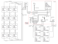
Looks good. One last thing that might be needed. With 3 pairs of batteries in parallel you may want to fuse each pair. What is the max continuous discharge current rating of the BMS in the batteries? If it's 100A then you should use a 125A fuse at the positive terminal of the left battery of each parallel pair. Let's say your inverter is powering a full 3000W load. It's now pulling 150A from your battery bank. Each parallel pair is contributing 50A. Now let's say that for some reason one battery in one pair shuts down. That leaves two parallel pairs left to power the 150A load. Now you are up to 75A from each of the two pairs. Still OK. Now let's say for some reason a battery in one of the two remaining pairs goes bad. Suddenly the 150A load is being sent to the one functioning pair of batteries but the BMS is only rated for 100A. Without separate fuses the over current protection of the BMS will kick in and shutdown the battery. With the separate fuses the fuse will blow before the BMS can shutdown thus better protecting the battery.
It's definitely a worse case scenario. You could get by without the separate fuses and rely on the BMS to save the last battery in this unlikely case. But the BMS should not be relied upon. It should only be there as a final safeguard when everything else has failed first.
It's definitely a worse case scenario. You could get by without the separate fuses and rely on the BMS to save the last battery in this unlikely case. But the BMS should not be relied upon. It should only be there as a final safeguard when everything else has failed first.
I wondered about that. So I will add those in. 125A fuse off of each positive terminal. Is there a preference on which type of fuse to use? ANL, T, or something else?With 3 pairs of batteries in parallel you may want to fuse each pair
Class T would be an obvious choice to handle each 24V 100Ah LiFePO₄ battery pair. Since you have the master 250A Class T fuse, it might be OK to use ANL fuses for the 3 parallel pairs. But I'm not sure about that. Class T would be best.
Ok, I will try to find them. I did find the ANL and they are quite cheap but the T would be better. Thank you so much for all your help.Class T would be an obvious choice to handle each 24V 100Ah LiFePO₄ battery pair
I bought my Class T fuse and its holder from Don Rowe:
High quality fuses at reasonable prices. Buying the kits ensures you get the proper holder. Class T fuses come in many different sizes depending on the amperage. It's easy to get the wrong holder if you try to buy the fuse and holder separately. Buy a spare fuse while you're there.
Class T Fuse Kits & Fuses | DonRowe.com
Fast-acting Class T fuse kits and fuses provide over-current protection for your batteries and cables, while helping to ensure safe inverter operation.
www.donrowe.com
High quality fuses at reasonable prices. Buying the kits ensures you get the proper holder. Class T fuses come in many different sizes depending on the amperage. It's easy to get the wrong holder if you try to buy the fuse and holder separately. Buy a spare fuse while you're there.
That is a decent price. I will go with them. ThanksI bought my Class T fuse and its holder from Don Rowe:
Similar threads
- Replies
- 4
- Views
- 276
- Replies
- 7
- Views
- 537