diy solar

diy solar

New EG4-8KEXP-240 Inverter

I am supprised as well, I think I first heard about them in late 2021, around the time of the Deye Sol-ark deal and the Deye inverters got kicked out of the US. I alwasy thought the Megarevo were just rebranded Deye inverters so I am surprised they made it to market here. I could be wrong about the rebranded Deye inverters.
They are not a rebranded Sol-Ark/Deye Inverter but another Chinese company attempting to clone some of the features.
I heard of Megarevo in I think it was Jan or Feb 2022 when that American solar seller from South America who is on the forum announced it as a replacement that he was selling for the Deye Split phase Inverters after Sol-Ark banned Deye from making them.
BTW his thread seems to have been deleted during the Seller Forum Purge of 2022.
 
Warning PURE SPECULATION FOLLOWS:

I wonder if tying the input and output neutral together is the problem with not getting the zero-grid controls working. My first reaction is no. As long as the two hots are not showing current there should be no power going to the grid. However, maybe something about the neutrals is creating a false reading.
I cannot imagine what you could do to the Neutrals to cause no current to register in the two Hot lines, except if there is really no current or the electrical path is not complete.
 
Last edited:
Will also commented that the manual was not clear about the N-G bond. (You have probably seen other threads with my rants about the lack of documentation about grounding and bonding before. Imagine another rant here) WILL: Did you ask Sig Solar about the bonding? If I followed the video, the set-up shown has the input and output neutrals tied together. Is this supported?
Your the only person that has tried to supply proper wiring diagrams for SS inverters so your Rants are justified.
Also I cannot imagine the N and G are bonded in the inverter. That would be a really bad idea and it could never pass a UL inspection.

BTW been looking for the UL listing and FCC listing numbers in the database with no luck. Maybe I am not looking at the right numbers on the Documents ?
 
At about 8:40 in the video @Will Prowse said he was checking for continuity while the inverter is on..... If he is measuring for voltage, that makes sense to me. If he is measuring resistance, I am not sure I would trust the results. The existing voltage on the circuit could certainly mess up the reading.

Will also commented that the manual was not clear about the N-G bond. (You have probably seen other threads with my rants about the lack of documentation about grounding and bonding before. Imagine another rant here) WILL: Did you ask Sig Solar about the bonding? If I followed the video, the set-up shown has the input and output neutrals tied together. Is this supported?
I did not ask them about the bonding which is why I checked it myself. Did not measure any continuity but good point about existing voltage. Did not measure any voltage AC or DC between the two. I did not use the output when the input was connected. There is a diagram that would show the neutral pathway.

And yes the documentation is driving me nuts. Did you read the manual? It's pretty awful. I sat in my thinking chair and tried to decode it and I had no luck trying a variety of configurations in the settings. Very frustrating.
 
Your the only person that has tried to supply proper wiring diagrams for SS inverters so your Rants are justified.
Also I cannot imagine the N and G are bonded in the inverter. That would be a really bad idea and it could never pass a UL inspection.

BTW been looking for the UL listing and FCC listing numbers in the database with no luck. Maybe I am not looking at the right numbers on the Documents ?
Good point. I'll look into that too.
 
Warning PURE SPECULATION FOLLOWS:

I wonder if tying the input and output neutral together is the problem with not getting the zero-grid controls working. My first reaction is no. As long as the two hots are not showing current there should be no power going to the grid. However, maybe something about the neutrals is creating a false reading.
On the display I get an accurate reading for voltage on the AC input. I checked for that before I changed the settings and added the load. I think the software is just funky.

It's also good to check to ensure that there's good connections on those terminals. Especially with the neutral. I like to verify every connection. Probably excessive but good to check.
 
And yes the documentation is driving me nuts. Did you read the manual? It's pretty awful. I sat in my thinking chair and tried to decode it and I had no luck trying a variety of configurations in the settings. Very frustrating.
I was going to read the manual but your reaction to it felt like a respected friend telling me how bad a movie is and then recommending that I see it for myself:LOL:.

I have already been forced to read so many of these chinglish manuals that I now get a headache mid way in.
 
Warning PURE SPECULATION FOLLOWS:

I wonder if tying the input and output neutral together is the problem with not getting the zero-grid controls working. My first reaction is no. As long as the two hots are not showing current there should be no power going to the grid. However, maybe something about the neutrals is creating a false reading.
Mabe I am missing something. Checking continuity while voltage is present? Did he mean checking voltage from point to point? Turn of the system disconnect power and check continuity via resistance. Mabe just his verbiage?
 
Warning PURE SPECULATION FOLLOWS:

I wonder if tying the input and output neutral together is the problem with not getting the zero-grid controls working. My first reaction is no. As long as the two hots are not showing current there should be no power going to the grid. However, maybe something about the neutrals is creating a false reading.
Leakage?
 
How old is the video? Have they corrected the software issues. 200 amp pass thru? This can be used to sell back
As discussed in this post & subsequent replies:

"I am not a solar expert but did my best to review the Spec Sheet & the User Guide & it to me it looks like it supports / recommends:

190A Charging/Discharging DC Current with Batteries (with 200A breaker);
33.3A Nominal AC Current Output to Grid (with 40A breaker);
36.7A Maximum AC Current Output to Grid (with 40A breaker);
40A breaker for the input from the Grid;

Both Load1 & Load2 recommend 40A breakers & it designates that Load1 is for "Critical Loads". I believe the guide is saying that Load2 will have it's power cut if the CTs detect that the Grid is down. I believe it is saying that Load1 will have power both whether the Grid is up or down (the wording could be better).

I don't see anything about a 200A pass-through. With the above info it looks like it at most can have 40A coming in from the grid & 40A out per Load breaker & the inverter is designed for 33.3 Amps (maximum 36.7Amps) Output & I assume that is spread across Load1 & Load2... ..."
 
Nice first post, do tell more.
What about different firmware?
I am not very sure about the firmware. I am seller who source goods from china for every 10 years now. As far as I can tell clearly that it is megarevo that makes them. they also make for some of bluesun models too and other brands as well. Wish I could tell you about that. but if you have knowledge, kindly do share it.
 
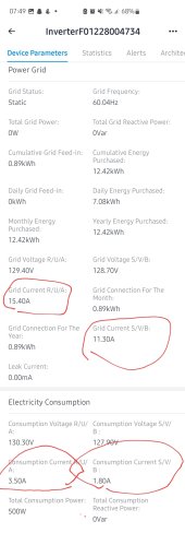
Does anyone know why grid current is always so high. Because of this the daily energy purchased value increases when nothing is being consumed from grid. The correct values are the consumption currents. I measured with a clamp meter.
The CTs are facing towards grid and anti reverse is enabled.
 

Attachments

  • Screenshot_20221227_075147_SOLARMAN Business.jpg
    Screenshot_20221227_075147_SOLARMAN Business.jpg
    137.6 KB · Views: 20
Does anyone know why grid current is always so high. Because of this the daily energy purchased value increases when nothing is being consumed from grid. The correct values are the consumption currents. I measured with a clamp meter.
The CTs are facing towards grid and anti reverse is enabled.
They r stealing from you sue them…? good luck with that Charlie … lol
 
How old is the video? Have they corrected the software issues. 200 amp pass thru? This can be used to sell back
Regarding the software issues, seems that Megarevo has been sending quite a few new updated firmware out. (Edit: By sending, I mean people have to bug MegaRevo for an updated firmware on Whatsapp)

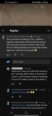
I saw this reply from him on another video that the manual had the L1 and L2 for CTs reversed.

I believe I read that on here on page 43 or 44 of the Megarevo RxLNA discussion as well.

Was hoping he'd do an updated video, but seems unlikely.
 

Attachments

  • Screenshot_20230216_014755_YouTube.jpg
    Screenshot_20230216_014755_YouTube.jpg
    170.6 KB · Views: 27
Last edited:
Back
Top