Patricktxfl
New Member
- Joined
- May 17, 2022
- Messages
- 27
Fairly new to solar and inverter setup. My second rv trailer with single 100ah chins lithium and Portable solar adding a renogy 1000w inverter on this one, all equipment new. My issue is with inverter, when I have attempted to operate trailer without inverter pos/neg connected and everything is okay on 12v, no solar hooked up.
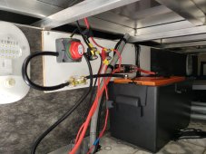
Simple system:
I have ANL on positive and off/on switch and Aili shunt on ground. Total length of 4 awg pre-made wiring is 4 1/2 feet between battery and inverter.
Positive 10ga jumper from fuse block to terminal block for solar and RV.
Negative 10ga jump from switch off side to terminal block for solar and RV.
When I connect inverter the battery bms seems to be seeing short and turning off before even turning on inverter. I originally had inverter mounted and grounded, and then tried isolated from frame ground.
When I first tried it seemed to test as positive grounded as I could switch off Negative side and use meter on dc test 13+ v between Negative battery terminal and frame, so seemed inverter was passing positive to frame.
I'm starting to think some type of DOA short, but thought I would ask before giving up. I've opened case with support, searched web and this forum for help. If you can help please feel free to give me your opinions.
Attached photo, Just FYI, the grey conduit and small black were existing trailer wiring and not part of system just crosses mounting board. I have not yet installed plug in fuse for solar or positive feed to shunt.
Thanks for your feedback