diy solar

diy solar

New inverter failure - fixed was pre-charge

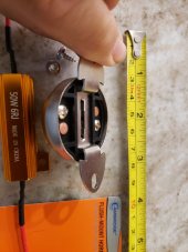
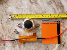
I would ditch the small wire and get a 6ohm resistor from auto parts store.
They sell a two pack for 12.00 in the light bulb section as an led load resistor for turn signals.
 
Thanks. I think you were right. I posted a reply to all, can you answer if my design to have a switch in negative is a design failure. Seems like switching off discharges capacitors so bms turns off again, and requires doing capacitor charge again.

Whether switch is in negative cable or positive, it removes power and capacitor will discharge over some time.
There may be a difference in what voltage appears at any terminals, like remote panel for inverter, or even AC terminals it those are not isolated.

As Supervstech says, resistor (or light bulb) could be better for gentle precharge. Wire can be used but may still come close to tripping BMS.
 
any continuity would show up as voltage.
Any difference in potential is voltage
testing with meter and was reading 12v between trailer frame and negative battery.
I think supervee missed that sentence. Or I’m reading it wrong. Or interpreted his post wrong
That scenario is only possible if neg and pos are reversed or pos is connected somewhere and neg is open.

That the equipment is shutting down and that you
Negative cable removed from battery. Frame to Negative term showed 13+v. Didn't think there was a path between them unless positive was shorted to ground.
…indicates a problem.

But any light or charger or whatever that is on (closed) with batt neg disconnected is going to do:
symptom that worries me was positive connected to inverter negative dis connected. I was testing with meter and was reading 12v between trailer frame and negative battery
Because your meter became path to ground
Negative cable removed from battery. Frame to Negative term showed 13+v. Didn't think there was a path between them unless positive was shorted to ground.
There’s always a series path if a meter or light or converter is left on - otherwise nothing would ever turn on. If something was shorted to ground a fuse would blow ending the 12V test.
 
Negative cable removed from battery. Frame to Negative term showed 13+v. Didn't think there was a path between them unless positive was shorted to ground.
Frame to negative terminal shows 13V+.

One of 2 things with that scenario, either you have a load connected that is passing current or the polarity is incorrect.
 
Frame to negative terminal shows 13V+.

One of 2 things with that scenario, either you have a load connected that is passing current or the polarity is incorrect.
A digital meter can help diagnose that if black lead is on neg and red on the frame. A negative voltage visualizing that scenario
 
Thanks guys for comments on the odd reverse polarity I saw on my meter. I'm so far from an electrical engineer it makes my head hurt even trying to understand the concept of how the meter was reading as it was.
The solution was pre-charge the capacitors. It's basically working correctly now so happy with that.

So now trying to setup a momentary switch to pre-charge since it's an RV install and often in storage for extended times so full battery disconnect needs to be in the plans.

It seems like a door bell and resistor should be able to supply the charge current. So I'm at the point of understanding the correct size resistor to order so to keep amps low so the door bell button doesn't have issues but not so low to extend the length of time it needs to pre-charge. It appears the 6 ohm 50watt resistors are more common than higher watt in 100 to 200 watt.

If one of you understand the equation or have built similar and you can share what worked for you. Single 12v 100ah lithium and 1000 watt inverter.
 
A car SB headlight bulb and a high-amp DC is a simple solution. Then the headlight between inverter and power precharges then you can turn inverter on. I think that would do it wouldn’t it? You need a resistance and not only resistors have resistance.
 
A car SB headlight bulb and a high-amp DC is a simple solution. Then the headlight between inverter and power precharges then you can turn inverter on. I think that would do it wouldn’t it? You need a resistance and not only resistors have resistance.
I like using light bulbs, because they glow as the capacitors draw current, and extinguish when filled.
So,ya turn switch to precharge position,and when the bulb goes out, you fully engage the battery.
Easy.
 
A car SB headlight bulb and a high-amp DC is a simple solution. Then the headlight between inverter and power precharges then you can turn inverter on. I think that would do it wouldn’t it? You need a resistance and not only resistors have resistance.
I understand lots of possible solutions. Just looking for small permanent solution. Momentary switch and resistor keeps it compact. Wasn't sure on size of resistor vs time required for my application. The ones often used in auto LED applications seem to be most readily available 6 ohm 50 watt versions i see are 1/2 x 2 inches, that at flush mount button push seem like an easy path to add.
 
I like using light bulbs, because they glow as the capacitors draw current, and extinguish when filled.
So,ya turn switch to precharge position,and when the bulb goes out, you fully engage the battery.
Easy.
Would like that concept for off grid cabin type install, but not practical in an RV cargo area.
 
I understand lots of possible solutions. Just looking for small permanent solution. Momentary switch and resistor keeps it compact. Wasn't sure on size of resistor vs time required for my application. The ones often used in auto LED applications seem to be most readily available 6 ohm 50 watt versions i see are 1/2 x 2 inches, that at flush mount button push seem like an easy path to add.
This is what I used for 2 of my inverters, one on the truck camper and the other on the truck for it's 2400W inverter. https://diysolarforum.com/threads/my-push-button-pre-charger-install-for-the-sw-4024-inverter.20426/
 
Parts came in. Horn button big 6a 12v. Large copper contact next to screw is also tied so screw and copper will make contact. Resistor has 20+ inches of wire on both sides gives plenty of length to mount and wire. Need to pickup some connectors, but should be a quick install. I'll put a meter on it and report the charge time tomorrow.
Switch $8.....(update just found button as low as $3.49 at napa auto parts) Resistor 4pcs came wired and some handy looking wire quick connects $5 Next day Amazon delivery. I probably made money as compared to driving my truck to the store at today's gas prices ;)
Thank you all for your input.
 

Attachments

  • 20220601_182843.jpg
    20220601_182843.jpg
    112.6 KB · Views: 6
  • 20220601_182706.jpg
    20220601_182706.jpg
    254.5 KB · Views: 6
  • 20220601_182754.jpg
    20220601_182754.jpg
    147.8 KB · Views: 6
Last edited:
Installed picture. Pre-charge only takes 2 to 3 seconds and bleed/discharge is almost as fast down to about 3v which means for smoothest switch I need to hold button while I switch then release. I installed with resistor wired to shunt, button to bus that allows the switch bypass.
 

Attachments

  • 20220602_091007.jpg
    20220602_091007.jpg
    214.1 KB · Views: 8
I believe you are experiencing a common problem with vehicle inverters. NEITHER SIDE OF THE AC LINE FROM THE INVERTER CAN BE CONNECTED TO THE SAME GROUND THAT YOUR INVERTER SHARE!!!! KEEP TRYING AND YOU WILL BURN UP YOUR INVERTER. There are NO grounded conductors similar to house wiring
Can you rephrase that? Doesn't the inverter internally bond ground to neutral so you don't die?
 
Only if your life is worth enough to you that you are willing to pay a fair price for the inverter.
Deciding to become active on this board sure has altered my proclivity to assume equipment is designed and manufactured to meet what one would expect for safety standards
 
Negative cable removed from battery. Frame to Negative term showed 13+v. Didn't think there was a path between them unless positive was shorted to ground.

Capacitors will look like direct shorts until they are charged.
 
I followed this threat somewhat and stopped when the OP (think it was the OP) solved his issue with a capacitor precharge whatever that means. Capacitors are charged using the formula V = C(di/dt) where the current i decreases as the rate of charge in C increases over time t.

Back to DC battery to AC inverters in general. BEWARE of so called vehicle inverters that properly work well most of the time. The inexpensive inverters that operate without transformers use what is known as an H bridge to output a square wave at whatever AC voltage it is designed for. Those outputs can be filtered electronically to sometimes an almost perfect sine wave. Hard for me to sketch a circuit using a keyboard but I will try to explain it.

Think of H where the top of the left side of H allows current to flow from it through the horizontal bar of the H leaving back the source at the bottom at H's right side. After that half cycle is competed, things reverse to the top right side of the H with current flowing in the other direction of the horizontal H bar.

The horizontal H bar represents where the AC load is. Notice that THERE IS NO GROUND FOR THE LOAD. This is important because Vdc is 170V. THERE IS NO AC GROUNDED CONDUCTOR EVEN THOUGH THE INVERTER TERMINALS ARE COLORED BLACK AND WHITE. IF YOU CONNECT THAT WHITE TERMINAL TO THE BATTERY GROUND YOU SHORT OUT THE INVERTER.
 
Back
Top