diy solar

diy solar

New LiFePO4 battery build, heat and voltage drop question

buckeyestargazer

New Member
Joined
Mar 15, 2023
Messages
25
Location
Valparaiso, IN
I just completed a battery build with EVE LF230 cells and have a question about the heat one of the components is generating.
Description:
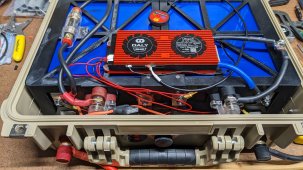
EVE LF230 cells, Daly 100A BMS
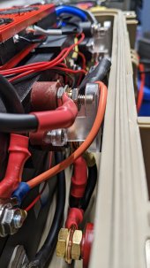
The cells are in series connected with the tinned copper busbars that came with the batteries
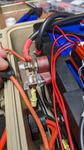
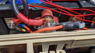
I have a 60A in-line fuse from the main Pos terminal to a 150A buss bar.
The BMS Neg is connected to a corresponding 150A buss bar.
Connected to the buss bars are 1/4" terminal studs, a 50A Powerpole connector, and two 30A Powerpole connectors.
I used 6AWG wire throughout, except the two 30A Powerpole connectors have 12AWG silicon wire, fused.

As a test, I connected a Krieger 1100W inverter and connected a space heater to it. (I had no idea those space heaters pulled so much power!) I turned the space heater on low and the BMS reports it is pulling about 52A or 670W at 12.9v.

Now I have two questions.
1. The positive buss bar got REALLY hot to the touch. It would burn skin. The positive wires (from the battery pos terminal to the 60A fuse and from the fuse to the buss bar) are also uncomfortably hot. All of the other wires in the system are cool or only slightly warm. The negative buss bar is quite warm but nowhere near as warm as the positive. Is this normal? Should I replace the 6AWG main wires with 4AWG?

2. The BMS reports the voltage at 12.9v under load. The voltage at the bus bars is 12.4v, but the voltage at the terminal studs is only 11.9v. Also, the voltage at the inverter is only reading 11.4v. The inverter wires are 4AWG with a 150A fuse. I'm just surprised that the voltage at the terminal studs has dropped a full volt despite using very short runs of 6AWG wire. Again, is this something to be concerned about?

Thanks in advance.
 
I'm not sure if you can tell much from these pics.
Also, I misspoke earlier. The two 30A powerpole connectors go right to the main positive terminal, not to the buss bar. I wasn't sure about that connection since I have a 20A fuse on that and wasn't sure how that would work with the 60A inline fuse.
 

Attachments

  • PXL_20230328_205833596.jpg
    PXL_20230328_205833596.jpg
    126.1 KB · Views: 38
  • PXL_20230328_205844101.jpg
    PXL_20230328_205844101.jpg
    110.3 KB · Views: 41
  • PXL_20230328_205853047.jpg
    PXL_20230328_205853047.jpg
    444.8 KB · Views: 38
  • PXL_20230328_210042748.jpg
    PXL_20230328_210042748.jpg
    308.8 KB · Views: 40
Here's something else strange. I mentioned that I put a 50A powerpole connector on the busbar terminals, and a 30A powerpole connector that is connected directly to the battery. I have a 20A charger. When I put the charger on the 30A powerpole connector the BMS reads 20.2A charge rate. When I put the same charger on the 50A powerpole connector the charge rate is only 14A. I just don't know what to make of that. Guess I'll have to tear it apart and examine.
 
Ok, so I think I've discovered the problem even if it doesn't exactly make sense. As noted above I have a 20A charger and I bought these terminal blocks/busbars. I discovered that if I have the red/positive terminal block in the line the charge current is only about 13A and the terminal block gets very warm, even at 13A. As an experiment I removed the terminal block and connected the wires directly, and now the charge rate is 20.2A and the wires get a little warm but not much. As a further experiment I put the black/negative terminal block in place of the red one and again got a charge rate of 20.2A and the terminal block did not get very warm. I repeated and put the red terminal block back in with the same result, 13A charge rate and very warm terminal block. I can't see anything wrong with the terminal block but it clearly behaves differently than the black terminal block. I'm going to replace both and see what happens.
 
Yeah those style bus bars seem to be a dime a dozen under various names.

Looks like you struck out on the Amazon lottery.

Can u measure the resistance of those bus bars?
 
Yeah those style bus bars seem to be a dime a dozen under various names.

Looks like you struck out on the Amazon lottery.

Can u measure the resistance of those bus bars?
I have a multimeter so I think I can test it, but I'm not sure how to interpret the results. Both busbars measured 3 ohms(?) when set on the 200 ohm setting.
 
Hm, didn't even notice that. I just saw 4-8awg 60A fuse.
Something like this?
Stay away from those car audio fuse holder and circuit breaker, the wire conductor gets crushed using the set screw.
 
3 Ohms? Does it have a coating or something that could be interfering and causing a bad connection? Corrosion ?
No, It's because I have no idea how to measure or read the resistance.

From your pics, it looks like you use the bussbar simply as a place to land the wiring…

I like to use these in my build.
Easily handles 200A and it’s solid copper, plus can be used as a battery box output port.

After a few more tests it is clear the problem is the busbar between the two screw studs. If I remove that busbar and simply use one stud to combine all the lugs the issues I was seeing disappear. Full charging current (20A in this case) and the wires etc only get slightly warm and no where near as hot as before.

So I'm just going to tie everything into one stud. Would it make any difference to replace the stud with a larger bolt or larger copper stud?
 
Or just buy a better busbar?
Yeah, no copper stud ^^. If you have to, use stainless steel.
 
You just described a bus bar ?

It does look like you have a tight space so I can see why a 2-5 lug bus bar is tough to fit in.

Just be careful with double triple quad stacking lugs, gotta make sure all surface area is prepped and properly toqued.
 
You just described a bus bar ?

It does look like you have a tight space so I can see why a 2-5 lug bus bar is tough to fit in.

Just be careful with double triple quad stacking lugs, gotta make sure all surface area is prepped and properly toqued.
If you can't tell I don't know all the lingo. LOL But I assumed that one threaded stud did not constitute a busbar.
I have another two post busbar on the way, similar to the faulty one but hopefully better quality. Each busbar will have three total lugs on it so nothing too crazy.
 
I think the issue is when double triple stacking lugs on one stud comes from maintaining proper surface area for everything, where as if you use on lug per stud you have only one current path/face and one clamping face.

This kinda goes back to the mindset of putting those bus bars as first connection to cell terminals, then stacking a balance lead then star but for clamping force.
 
Back
Top