diy solar

diy solar

New NinjaBatt 560wh Not Powering On - Quick Fix?

cflugstad

New Member
Joined
Jul 8, 2021
Messages
7
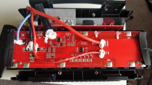
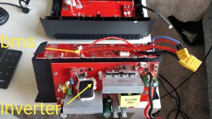
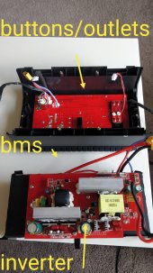
I just got a NinjaBatt 560wh for my boat/camping, and unit will not power on. When I plug in a charger, the display lights up, unit says its charging but is accepting 0watts(so its not charging). When plugged in and "charging", i can run DC outlets, usb, etc but the inverter does not work. Opened the unit up to see if there were any obvious culprits. found none. Things were secured quite well.

Is this a known common problem? has anyone else experienced this with a powerbank? Hoping there is a process to fix this unit.

Much appreciated.

Chris
 
Welcome to the forum.

Never heard of a NinjaBatt. Have you contacted the manufacturer?
 
@snoobler - Yes. They have no help just communicated the unit was defective and were not able to ship out a new unit. customer service kinda lame. I think the company is a joke. When you call them its another battery company name, and tech support is just a triage where you never get a response. Relying on nerds/geeks/hackers like you to put some life back into this unit rather than throwing it in the garbage.
 
Nerds/geeks/hackers would generally opt to DIY for better value and reliability.

When you opened it, were you able to access the battery?

If so, did you measure the voltage of the cells/battery?

If so, what were the values?
 
it appears to have 5 groups of cell banks/groupings. When I test first, 3.7, then 7.2, then 10.9, 14.5, 18.2 21.8 (all)

When I test voltage on the main leads from the BMS on the battery, i get no voltage. Im wondering if the BMS is the issue, and it will not supply power to<>from the inverter/DC outlet, and the inverter/DC outlets turn on when i plug it in because they are being powered from the charger.

Also have nothing else to compare this to to see if wired correctly. I am not an electrical engineer either.
 

Attachments

  • ninjabatt.jpg
    ninjabatt.jpg
    341.4 KB · Views: 5
3.7
3.5
3.7
3.6
3.7
3.6

A 0.2 deviation is pretty disappointing. On a new product, I would expect less than a 0.05V deviation.

Since you have voltage at the cells, but not past the BMS, it's likely the BMS as you suspected; however, it might also be because of the 0.2V deviation in the cells. Some BMS will trip on that basis alone, not just because one is out of limits.

A common BMS reset procedure is to short B- and P-

Typically B- is what connects the (-) of the battery to the BMS and P- is what connects the BMS to the main (-) terminal where the charger/inverter (sources/loads) are connected. That would also explain why you have partial function of the DC systems when charging (charger is attached at the main (-)), but not the lack of inverter function.

It might be that the inverter has an internal short, and the short-circuit protection of the BMS is activated. If you can disconnect the inverter from power, that might be diagnostically useful. If BMS works with inverter disconnected, but not when inverter is connected, inverter likely has internal short.

Additionally, if you have the ability to charge the entire battery or individual cells closer to the 3.7-3.9V range (never exceed 3.9V on any cell), that might also be useful.
 
I agree the cells are not optimal, but shouldn't that change with discharge/charging if it were to function? also shouldnt it at least work?

so now i have separated all parts. battery is soldered to BMS. inverter is disconnected but attached to battery. switches and outlets are disconnected.

I am stil getting no voltage on either of the leads from the BMS. this makes me still think its not giving off any current due to wiring, or BMS is malfunctioning. I'll try to short B- and P-. Tring to figure out which one is P-

other than disconnecting the 110v outlets, the inverter is soldered to the board, so not sure how to find a short if there is one.
 

Attachments

  • ninjabatt2.jpg
    ninjabatt2.jpg
    349.9 KB · Views: 6
  • ninjabatt3.jpg
    ninjabatt3.jpg
    140 KB · Views: 6
Different BMS work in different ways. Some BMS don't care about balance and simply cut off when any single cell goes out of limit. Others may cut out if the total voltage difference is outside some limit.

Based on the pictures, I would conclude P- is the large black wire from the BMS that connects to the inverter.

Before shorting anything, it's worth checking voltage between the two contacts.
 
So the big black wire to the not so big blue wire. I feel like im defusing a bomb in a movie ;)

i checked voltage from the Black P- to the Blue B- and got no volts. Shorted, and nothing happened. Tested voltage after on +/- and nothing. also I am testing on the board, not just the end of the wires, thinking there might be a bad connection. Still nothing.
 
If the big blue wire ultimately connects to the (-) of the battery, yes.

We have reached the end of any expertise I might claim to have. Good luck.
 
thanks for your help.
I have concluded it is the BMS. I removed the front plate/outlets/buttons. when i plug in the charger, it does exactly as it did before. dc ports work, and im going to assume they are simply running off the voltage being plugged in. The inverter doesn't work, because there is no power/current being delivered from the battery via the BMS. If i was going to do a repair, i'd try and wire a new BMS onto this unit. Sadly, i dont seem to find the board, even though i have the part number. BMS-PPS500-5. I did find another product very similar, where the reviewer said the same problem and concluded the same after tearing apart. I am finding a lot of chinese manufactures who make these products but none of the parts. i wouldnt really want to spend the 10-20 hours more to rewire a BMS and that might not even fix it.

so if anyone wants some parts, hit me up ;)
 
Back
Top