diy solar

diy solar

New no battery pure sine wave solar power system with smart switchers.

GridWorks Green Solar

Solar Innovator
Joined
Sep 30, 2022
Messages
1,029
Location
USA Tennessee
Introduction: Hi all, I am not a company or business of any kind but a retired tech that is trying to win at this new green power transition, this project deals with mains voltages (126) VAC! (181) VDC! will require correct wire sizes,fusing, insulation and isolation transformers to interact with other solar or grid power systems.Do not attempt anything you read or see in this thread unless you are comfortable working with high voltages!
After 7 years years of solar power in my home Gopower IC3000 the 4 deep cycle batteries started to degrade and needed replacement, after spending one arm and a leg in replacement cost it dawned on me everything I had saved over the past 7 years just went into new batteries!
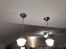
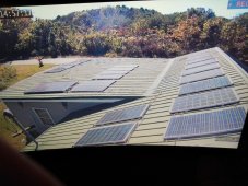
This project from the ground up is a no battery,no charge controller, no maintainance and fully automatic normal day (2 second grid/green transfer at 9AM) (2 second green/grid transfer around 6PM). This new starter 800watt system powers the lights,fans,bug zapper, security cams and mini fridge daily in my home. Basic system consists of 9 one hundred watt solar panels 181 VDC in series and a pure sine wave output power board, please allow me some time to upload all the data and pictures. Hope to help others save money and get the power back on from the damage to Florida.

Major steps forward please read page 22 to the end of thread for all the best bells and whistles, successfully providing main Air conditioning to the four largest rooms in my home 95 degrees Fahrenheit outside 74.8 inside at 5:30 PM. Exceeding my expectations.
 

Attachments

  • IMG_20220908_125529967.jpg
    IMG_20220908_125529967.jpg
    160 KB · Views: 365
  • IMG_20220905_151640057.jpg
    IMG_20220905_151640057.jpg
    298.2 KB · Views: 371
  • IMG_20220821_163618394.jpg
    IMG_20220821_163618394.jpg
    174.8 KB · Views: 363
  • IMG_20220906_100314608.jpg
    IMG_20220906_100314608.jpg
    151.5 KB · Views: 352
  • IMG_20221014_131012688.jpg
    IMG_20221014_131012688.jpg
    190.1 KB · Views: 311
Last edited:
Interesting.
So, it is only for daytime power? If the grid is down, it does nothing at night?
Looking forward to see more on this.
 
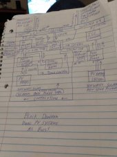
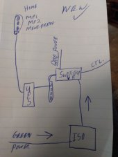
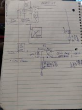
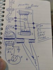
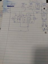
Block diagram as builts of the new system is on the right ?
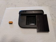
Solar sensor two 3 volt small solar panels and DPDT relay.
 

Attachments

  • IMG_20220928_145704257.jpg
    IMG_20220928_145704257.jpg
    284.7 KB · Views: 189
  • IMG_20220824_114832535.jpg
    IMG_20220824_114832535.jpg
    226.9 KB · Views: 152
  • IMG_20220915_112817025.jpg
    IMG_20220915_112817025.jpg
    172.8 KB · Views: 175
  • IMG_20220924_194453259.jpg
    IMG_20220924_194453259.jpg
    126 KB · Views: 193
Interesting.
So, it is only for daytime power? If the grid is down, it does nothing at night?
Looking forward to see more on this.
Just one of the things this little power systems does well is charging LI-ION batteries, fully charged my green mower in less than two hours.
Also smart switchers can work with secondary power source or UPS.
 
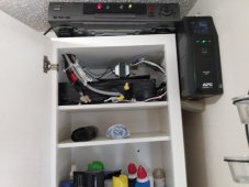
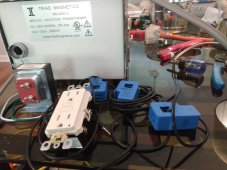
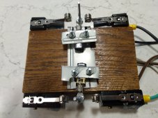
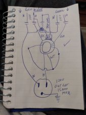
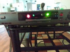
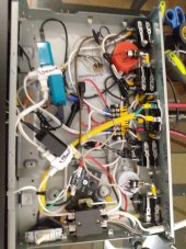
Fault detector circuit with GFI trip protection, overview, getting ready to build a switcher, have three working switchers,side by side fridge, Mini split heat pump, and new power system, deluxe switcher has 7minute delay for restarting the mini fridge.
 

Attachments

  • IMG_20220910_122034058.jpg
    IMG_20220910_122034058.jpg
    259.4 KB · Views: 99
  • IMG_20220827_113117540.jpg
    IMG_20220827_113117540.jpg
    105.7 KB · Views: 94
  • IMG_20220825_110233584.jpg
    IMG_20220825_110233584.jpg
    83.6 KB · Views: 89
  • IMG_20220828_084803090.jpg
    IMG_20220828_084803090.jpg
    159.9 KB · Views: 94
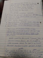
Details: version 9 logic relays, ruff drawing of R2 reverse actuators detail, and the start of instructions manual, PM me if you need more information or photos.
 

Attachments

  • IMG_20220930_115048048.jpg
    IMG_20220930_115048048.jpg
    109.2 KB · Views: 46
  • IMG_20220930_114736037.jpg
    IMG_20220930_114736037.jpg
    159.5 KB · Views: 48
  • IMG_20220930_113453968.jpg
    IMG_20220930_113453968.jpg
    130.7 KB · Views: 44
  • IMG_20220930_112933461.jpg
    IMG_20220930_112933461.jpg
    119 KB · Views: 40
  • IMG_20220930_110038285.jpg
    IMG_20220930_110038285.jpg
    90.3 KB · Views: 43
I have videos in MP4 format that show the three switchers in action, and the GFI fault detector and grid trip,
 

Attachments

  • IMG_20220814_155219603.jpg
    IMG_20220814_155219603.jpg
    230.4 KB · Views: 43
  • IMG_20220802_112803049.jpg
    IMG_20220802_112803049.jpg
    154.2 KB · Views: 43
  • IMG_20220916_205049859.jpg
    IMG_20220916_205049859.jpg
    253.9 KB · Views: 43
Existing new system maxes out around 800 watts on a 1000 watt pure sine power board, although I don't yet have the additional PV panels I am building up a 2000 watt pure sine board that will produce around 1600 watts of clean usable power. Making the max output less than the power board ratings makes these things bullet proof to hard use and abuse, simple power down reset restores operation.
Testing mini split switcher on the right.
 

Attachments

  • IMG_20220914_140746014.jpg
    IMG_20220914_140746014.jpg
    224.9 KB · Views: 29
Last edited:
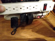
Surge suppressor power strips cause nothing but problems with the switcher systems avoid them, only other fault was a tiny spot of epoxy glue on the inverter 15amp micro switch, that expensive cube inverter let out it's magic smoke, take great care to keep the switches/actuators clean from glue, silicone and metal chips.
Never touch the micro switches once the switcher unit is energized!
 

Attachments

  • IMG_20220921_103835034.jpg
    IMG_20220921_103835034.jpg
    198.7 KB · Views: 22
Last edited:
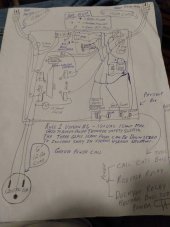
Here is a ruff drawing of version 6, Version 9 has many improvements like dual Metal geared actuators, Quad series switching for the hots, Quad series switching for neutrals, more than one switch would have to fail at the same time to have a fault condition ?
Version 9 logic will seek out anything hot with the green call enabled, will disconnect switches from grid if grid power is lost for any reason.
 

Attachments

  • IMG_20220821_163618394.jpg
    IMG_20220821_163618394.jpg
    174.8 KB · Views: 60
  • IMG_20220930_200334355.jpg
    IMG_20220930_200334355.jpg
    129.2 KB · Views: 60
Last edited:
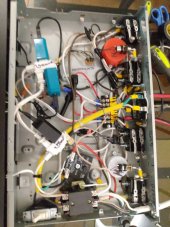
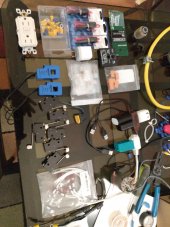
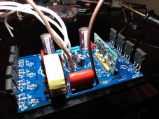
Just finished soldering up a 2000 watt pure sine wave power output board, consumed two of the 1000 watt kits to make it.
This power board will require 18 one hundred watt solar panels in two 9 panels series strings target voltage 180 volts DC 5amp glass fuse for each string of 9, for a target of 1600 watts of clean usable pure sine wave power.
Next comes testing and putting it in a old inverter case?
Have three new 1000 watt pre assembled boards 2 still in the plastic bags ?
 

Attachments

  • IMG_20221001_183503322.jpg
    IMG_20221001_183503322.jpg
    250.6 KB · Views: 45
Last edited:
My personal aim is a $40 a month electric bill, last three were around $80, neighbor across the street just paid $300 for last month.
None of the 220 volt appliances are on the solar system, but the new heat pump mini split is 120 volt and for the past week has carried the day time A/C needs nicely.?
After hours grid power through the Gopower system comes at a 20% additional cost, using the smart switchers shifts the after hours load directly to grid saving more money, These new power board systems work over a wide range of sun brightness as long as you don't fully load the system, normal drop to grid happens just before it starts raining or close to 6PM in the afternoon.?
 
Wish I could get get the word out to the people in Florida who many will not have power for months, to test the new pure sine wave power system, the only expensive part is the isolation transformer for interacting with other negative ground green power systems or grid power systems, most people just need lights fans and a way to charge the cell phone, 9 solar panels and a single power board can do that and more.
 
Last edited:
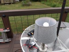
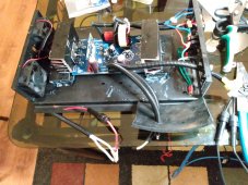
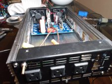
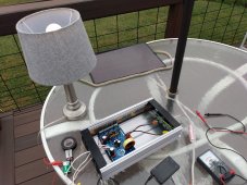
2000 watt pure sine power board mounted in an old inverter case and ready for testing. Going to test it as an off grid system on the back deck using a smaller solar panel 14VDC around 30 watts to run the CPU and fans from a switch. Wish me luck, I will report back about this test.?
 

Attachments

  • IMG_20221002_073732591.jpg
    IMG_20221002_073732591.jpg
    257.8 KB · Views: 41
Last edited:
Amazing news, first time testing the pure sine wave power boards in off grid mode. Not the best conditions overcast sky due to hurricane Ian and using a 14 volt DC solar panel for the CPU and fans when spec on the pure sine wave power boards is 16 volts AC or DC. New 2000 watt kit preformed perfect after running the CPU and fan on 18 volts DC from two nine volt batteries, the 1000 watt pure sine board has no issues running off the 14 volt DC panel and the 9 one hundred watt solar panels on the roof in series at 181 volts DC. ??
 

Attachments

  • IMG_20221002_130532493.jpg
    IMG_20221002_130532493.jpg
    320.2 KB · Views: 41
  • IMG_20221002_125521057.jpg
    IMG_20221002_125521057.jpg
    336.5 KB · Views: 40
These power boards will output 240 volts AC with a PV input of 380 VDC,220VAC out at 360 VDC input,120 VAC out at 180VDC input.
Just direct drive FETs no step up/down transformer, when interacting with other negative ground solar power systems or grid power systems you must use an isolation transformer to block this negative ground DC bias, in other words you must divorce this pure sine wave power from it's DC origin, DC power cannot pass through an AC transformer ( secret to car charging on solar, running a mini split on solar and interacting with other power systems!)
Pure sine power board will explode if you don't address this DC bias at the moment you connect it to another power system, last one looked as if high voltage DC invaded the low voltage side of the pure sine board.
After the isolation transformer all you have to do is bond neutral and ground to earth ground and everything loves the pure sine wave green power ?
Also recommend use of a 16VAC door bell transformer for the CPU and cooling fans on the pure sine boards as isolation from the strong bias to other power systems.
What you may not have noticed is except for the roof top solar panels I built up two independent power systems in just two days that will eventually net me an additional 2400 watts of pure sine power. It can change your life, you don't need to feed it gas/diesel in fact 1440 watts of pure sine wave power will run most level one EV car chargers, new three quarter ton 120 volt mini split heat pump only pulls 800watts after starting ?
 
Last edited:
Please spread the information in this thread to others, especially to those in the Ft. Myers and surrounding areas of Florida looks like a bomb went off in some areas.Thank You ?

I don't have normal social media accounts (Face Book, Twitter,ect.)
This new concept of a no battery, no charge controller and no maintenance direct drive solar power system is a big deal, with the addition of the smart switchers and sun sensor control concept makes it a totally new way to do solar or other green power, Please help me spread the word.
 
Last edited:
Notice that the ninth solar panel in the string for new power system was catching a heavy shadow in the afternoon from an off air antenna and security cam, electrically swapped it out with one that suffers no daily shadows.?
also tested and put several mixed panels on a Mppt charge controller for the Gopower unit.?
 
Last edited:
I don't see anyone doing it, but two panels in parallel in a shaded location could be a cost effective solution compared to optomizers and the like.
Never thought of that but it makes perfect sense, trying to come up with a second string of 9 to put in parallel to double the output power of the new pure sine system. Right now I only have seven and reluctant to spend more money. Maybe as a test the Epever 100amp controller runs on two strings of 6 panels in parallel, borrow a set of six and add three to run a max output test on the 2000 watt pure sine wave kit I built.
PSA caution three panels or more in series can kill you! One reason I like working on them in the pre dawn hours?
Also I know high voltage is dangerous but it is far superior to low voltage high amps (heat hot wires, fuses and connectors in the old days!) DC flows efficient at higher voltage smaller wires just be careful, use proper fuses,wire type/size and switches, house hold switches you get from Home Depot will weld closed under High voltage DC and get you killed ( never touch a DC circuit until it is confirmed off and dead! You must discharge any high voltage capacitors before you physically touch the wires/board)
?
 
Last edited:
I'm trying to understand your system, could you write a bit more about why you have different switchers, and how to build your direct pure sine inverters?

The first thought on reading your posts is how does it compare to a recent model hybrid inverter, most of them can operate in batteryless mode without grid or a battery, just MPPT solar direct to 240 or 120 V AC output. I'm not sure if you can tell them to ignore grid power during the day but if there is enough solar then they'll use that first instead. You could always put a switcher on their grid input to cut it off too.

The advantage over your direct DC => AC inverter is that you don't need to match the string size to the AC output voltage. Also, solar panel voltage (Voc / Vmp / etc) is *pretty* stable but not *that* stable, especailly over a temperature range.

I've built something similar to directly charge my EV from solar, but I put in a buffer of hybrid lithium super capacitors (surprisngly cheap!) because the car can take a few seconds to drop to a new power level when a cloud goes over. You can charge most EVs on as little as 600 W, because their OBCs generally accept a wide voltage range (mine is 85 to 265 V), and the charge protocol between the EVSE and the car just controls the max current the car can draw. The minimum is 6 A, so I can charge at 100 V and 6 A => 600 W. It is pretty slow but better than nothing :)

It'd be great to charge the EV directly with DC at the panel voltage (you don't need a lot of panels either if you make your own, because you can increase panel voltage by cutting and shingling cells), but the protocol to get direct access to the battery is a nightmare... still on my TODO list.
 
The switchers are different because I am testing different assembly methods, the side by side switcher has the smallest set of 15amp micro switches (4) but is the most complex fault detector with GFI trip and level 9 relay logic also runs a 5 minutes (adjustable) delay and indicator light for an easy restart of the side by side fridge compressor.
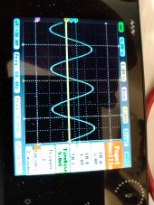
All the switchers have been upgraded to the three DPDT relay version 9 logic, the deluxe switcher offers more robust (8) micro switches, all outputs are routed through two switches in series to make the chance for a fault condition very unlikely, unit has two different outputs first switches in two seconds the second is time delay .25 to 7 full minutes intended to restart compressors. The sine wave power voltage changes with load around 126 VAC at 50watts to 108 VAC under full load.
My sun sensor approach either transfers to grid or a second power source or turns off the solar power if the sun energy is too little, system has not messed up in a long time, last fault on the new system was due to not enough delay time on the mini fridge compressor restarting (needed 7 minutes not 5) this stalled compressor made the lights go off, pure sine power system needed the CPU rebooted to recover from the fault.
These pure sine power boards are sold to upgrade modified sine inverters to pure sine or make repairs to a blown output FETs in the output section of almost any inverter. the replacement power board is made to fit most inverter cases.
My guide has been to use cheap off the shelf common parts to keep the cost down, the magic is all in the gaps and spacing between the switches, you can do it all electronically but any mistake will let the magic smoke out of your inverter.
My way of thinking says one switcher for each major appliance or 15 amp max circuit ?
 
Last edited:
Think I have a good idea to do a true full power full load test on the 2000 watt pure sine power board.
Take the 12 panels going to the new Epever 100Amp charge controller and put them in series minus three and parallel it with the other string of 9 panels, will do this test over the next couple days ?
Solar day just ended on the new power system 5:53PM 2 second transfer to grid, perfect solar day once again ?
If you were off grid the transfer could be to generator or another power system inverter or some other source of green power ?
 
Last edited:
Did the new power system and switchers at the kitchen table in a couple months, project included advice from a licensed electrician and IT expert, when compared to my other power system this one just makes me happy when the lights flash and I realize nothing was on grid for the past 9 hours?
 
Thank you for the explanations, I get it now. I didn't know these pure sine upgrade/replacement boards existed off-the-shelf and was planning to make something like that myself for testing (or extract from a standalone inverter)... excellent.

The solar-all-day approach is very appealing but we've had atrocious weather where I am the last 3 years, so it would have seen little use :(
A batteryless all-in-one inverter/charger unit would be easier than switchers, but not half as rewarding :) — the 2 second transfer is actually a bonus because you can notice it, nice.
 

diy solar

diy solar
Back
Top