diy solar

diy solar

New no battery pure sine wave solar power system with smart switchers.

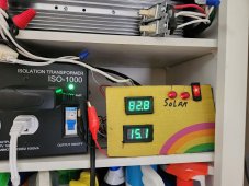
Reorganizing both old and new solar power systems to maximize summer time usage and savings.

Will make a serious effort to automate the whole thing sending after hours loads directly to grid is a big part of the plan.
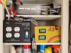
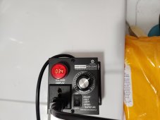
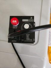
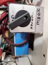
Also have a master home Grid-Off-Solar switch that needs extended to the new directly driven solar system. One switch to totally bypass everything solar just in case it would be needed.

More to come ?
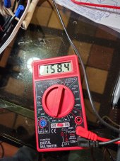
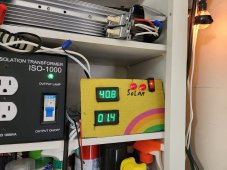
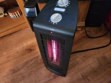
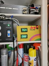
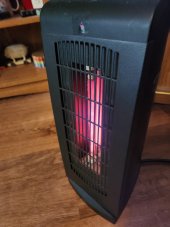
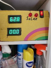
What is happening right now at 4PM late in the day and cloudy (Big power 1130 watts and zero secondary ?), Home bypass switch picture.
 

Attachments

  • 20230313_161048.jpg
    20230313_161048.jpg
    144.2 KB · Views: 4
  • 20230313_160919.jpg
    20230313_160919.jpg
    88.4 KB · Views: 4
Last edited:
Amazing work, and I hope you get to the point of having something to sell, soon! Thank you for this effort!

(It will take several readings to get through all the pages/posts!)

I'm going to have to go look for the old information, in the BMS sub-forum(?), but I could've sworn that something like the "electrodacus" was also supposed to be capable of similar activity, where X number of panels + electrodacus = daytime power?

In any case, again, what great work! It's electronics benchwork like this that makes for great idea sharing, great "maker" activity, etc.
Anyone that wants to turn this into a business has my full permission, I will even assist you in the endeavor.
Reviewed two failed grid tie installations in the south east one $39000 and one $69000 25 year payoff, what I am offering is $80 per panel and $50 per powerboard and you can do it all in a few weeks yourself and expand as needed, recommend to start 18 standard 12VDC solar panels 100watt and a 2000 watt pure sine power board. With secondary power
support it is easy to make things run on a day to day basis with out the expense of deep cycle battery's.

Hope to inspire others to make something of this unique power board system.

Even on a heavy overcast sky normal to get 300 to 500 watts power production, full sun will provide 1500 watts continuous power from 18-100 watt PV panels. Makes me smile every time, 120 volt leaf blower is like a jet engine in full sun, doesn't just run your stuff quartz tube heater radiation can be felt on your face across the room.?

YouTube has videos in every subject to assist you in properly installing solar panels to installing the power board FETs in a case, if you review this thread for warnings and build information most things are not that hard when you have seen it done, if unsure wear rubber gloves and make sure capacitors are discharged before you work on anything.

Use proper DC switches,glass fuses and wire, the system and power boards can be tested with low voltage 12-18 VDC or meters from end to end before first power up.
After high voltage test pass or fail you must assume the capacitors are fully charged, I use a standard 40 watt appliance bulb to discharge the capacitors before servicing the units.
 
Last edited:
I am sure someone has come up something similar, but this system is the results of 6 years of study and trail/error
The difference with me is every set back has led to the next big leap forward through not taking no for an answer.

The key is PV voltage of 180VDC naturally becomes 120VAC when passing through switching FETs. Secondary power support with 120 VDC allows for seamless operation even with passing clouds also sets up a natural power blend where the primary PV 180VDC has the advantage and blocks the use of secondary power.
Solving the ground bias issues with ISO transformers has made the unit rock solid reliable also thanks to user/forum input the unit now is super efficient 83%.
The only improvement left is to increase the DC secondary voltage from 115-120 VDC to 150-160 VDC won't really make the unit more efficient but the user will benefit from being able to run more stuff 24/7 without regard to sun conditions.

Not quite finished yet, planning one additional set of 9 PV roof top panels on the new system, I am not the one to do this but the basic plan can be scaled up to a huge power system with much higher voltages AC and DC the FETs used in the current project are rated for 600 volts and 40-60 amps, the board is designed for 380 VDC input at up to 3000 watts, simply building up the traces can get you 4000-5000 watts range.

More to come ?
 
Last edited:
The power board system can be custom configured for many different usages.

In my home an older deep cycle battery solar system 3000 watt is backings up several of the new systems for CPU,fan and secondary power support, at 5-6 PM all larger loads are dumped directly to grid for the night, I use time, system status and solar sensor to control three of the switcher units, the deluxe switcher on the side by side fridge,mini split switcher and one more yet to be assigned a task.

The reason for switching directly to grid at night is the after hours secondary power on both the old and new systems is a 20% extra cost, If lightly loaded the new system is closer to 15% extra costs.

Since before the past two upgrade cycles the system has preformed flawlessly day to day, went from 65% PV efficiency to 83%, most of the PV array is 5 years old and has been recently cleaned ?

After much consideration I have decided to add windings to the secondary ISO transformer to boost the voltage from 120 to 150/160 volts simply the most efficient way to get a higher output DC from the transformer and diode bridge. Main thing is removing or putting a clean hole in the tar slug in the center of the toroidal transformer.
Wish me luck, any mistakes will cost over $200 for a new transformer.

Pictures and info will be shared when successful, more to come
 
Last edited:
This is the most DIY-ish thread I’ve seen on this entire site. I salute you sir.
 
This is the most DIY-ish thread I’ve seen on this entire site. I salute you sir.
Why thank you, Here is some major DIY, over shot the mark by 9 VDC but can remove windings till I get it just right as a experiment going to install and test the secondary at 169 VDC ISO transformer.
Added a secondary winding to the ISO of 52 volts plus the factory 117 equals 169 volts was aiming for 160 VDC.

Lucky me no tar in the center of the toroidal transformer only one large bolt now packed full of DIY secondary windings, used 12 gauge stranded wire with a double insulation coating.

Took about three hours on the back deck, wire ties and clips are helpful in the process. Started at mid point with new 100 foot wire and wound each direction only good part is the wire gets shorter as you go along. Was not able to use the whole 100 foot because no more room for windings through the central hole.

Still fits in it's case ?
Transformer will sit on a thick rubber pad when finished.
On second thought going to keep it on the work bench till it produces just under 160 volts DC math says it will be the sweet spot, wire ties will be added to bind the windings tightly.


More pictures soon,more to come
 

Attachments

  • 20230315_134450.jpg
    20230315_134450.jpg
    376.5 KB · Views: 9
  • 20230315_161033.jpg
    20230315_161033.jpg
    150.6 KB · Views: 10
Last edited:
Success custom secondary winding 42.5 volts 63 full turns of 12 gage wire 158.4 VAC 144 VDC out to the power board.

Will reinstall tonight with some real world testing of secondary power.

Think the DC voltage meter would be higher if a filter capacitor was on the output, close enough to test what I am looking for, going from 117 to 158 on the AC side, 115 to 144 VDC nice boost to the power board without overwhelming the natural power blending features that shuts down secondary power usage when PV voltage hits 180VDC.

More soon
 

Attachments

  • 20230315_175654.jpg
    20230315_175654.jpg
    197.6 KB · Views: 1
  • 20230315_175737.jpg
    20230315_175737.jpg
    288.8 KB · Views: 1
Last edited:
Amazing improvement old after hours maximum system draw 5.3 amps new test passed 7.3 amps, it will do more but I don't want to blow something up.
The real test comes later with full sun PV power blocking the secondary feed.❤️

That is 7.3 amps out of a maximum 10 amps that will trip the ISO breaker or blow glass fuse.

Just doubled seamless secondary power support from 600 watts to 1200 watts only need 800 to make the mini split happy.?

BTW the power supply for the displays can handle 240 VAC input voltage will be fine at the 158 VAC off the ISO transformer. Everything is a notch brighter now.

As always more to come

Anyone spot a problem??
ISO green led is being over driven, spotted it in the photo not in real life.
 

Attachments

  • 20230315_195901.jpg
    20230315_195901.jpg
    246 KB · Views: 3
Last edited:
Right now I must wait for full sun conditions to see how the power blender works, may very well be over driving secondary voltage.
(Added later on officially overdriven results for the power blender very little PV gets through secondary input but now that I see it work full on giving anything back is off the table)
but it is easy to adjust the downwards direction, testing confirms I will soon find the best spot to run the system over the next few days, may even put in a switch for multiple levels of seconday power operation.

As of right now the system is pushing a higher output level than ever before but is pulling 1/3 less secondary amps at night time, will be extremely interesting to see where this all lands after final adjustments.

Think I have hit another home run but it will take a few days to work everything out❤️

You will be provided all the data once it gets my final approval ?

I smell victory just around the corner, some will regret not getting started sooner on this power board project.

Early indications are several downward adjustments will be required, with my old system if you set shore power amps too high the thing spends all it's time pulling grid power instead of being a PV solar power system, similar thing going on right now with the new system.

Right now if I turn on the ISO transformer 5 amps transfers from solar to secondary, If I turn off the transformer there is a noticeable voltage drop and the 5 amps transfer is to solar PV. Not wanting to give up the big gain in secondary power support I need a better solution. This may take me a few days to figure out but a elegant solution exists, plugging the ISO transformer into a system status controlled grid outlet sounds promising but would likely end up surging the system and causing damage. Must consider everything before proceeding forward.

Picture ISO transformer turned off all solar right now.
 

Attachments

  • 20230316_095946.jpg
    20230316_095946.jpg
    169.8 KB · Views: 3
Last edited:
1st Picture heavy loads both power boards, ISO transformer secondary is turned off all solar power.❤️

2nd picture same load with it being dark outside.

I don't want to give up anything I have working right now, must come up with the perfect solution.

Easy with one normal 24/7 ISO transformer for secondary 600watt 115 VDC out backup power and one grid powered ISO modified for higher output voltage for after hours usage 1200+ watts 144VDC out run off a timer, hope to come up with something even better.?

A system to ramp up the ISO grid power primary power as system output AC voltage falters may be the holy grail solution to this system problem?
I see a couple of inverted transistor circuits making this fully automatic.
 

Attachments

  • 20230316_103956.jpg
    20230316_103956.jpg
    258.3 KB · Views: 2
  • 20230315_195901.jpg
    20230315_195901.jpg
    246 KB · Views: 2
Last edited:
Made a decision going with off the shelf standard 120 VAC 15 Amp speed motor control with knob adjustment for the secondary ISO transformer, expect maximum 9.5 Amp in normal operation.

This will allow the user to custom tune the low preset level of secondary power system operation, my solar sensor runs a nice relay that will open by day and close the contacts to bypass the speed controller at night shifting the ISO to the higher 1200+ watt mode.?

It is simple and it will work out well, user will control everything, you will need to know the PV live current amp draw to adjust knob properly for example if you turn the ISO transformer up to full (ON) it won't process much of PV power, turn it (OFF) and you will not have secondary power at all system will falter if you don't have enough sun PV input.

not a perfect solution but it fits into the general plan of the project, also it will allow fine tuning the natural power blender for maximum efficiency, bottom line it will work.❤️

Part ordered.
 
Last edited:
You’re getting there!
So close, very very close?

Part due in tomorrow, has rained most of today, running bright and steady on boosted secondary power.

Looking forward with being able to fine tune the natural power blender, many advantages similar to MPPT efficiency increases will be available to the user with the control knob.

More later.
 

Attachments

  • 20230305_111026.jpg
    20230305_111026.jpg
    243 KB · Views: 4
  • 20230315_195901.jpg
    20230315_195901.jpg
    246 KB · Views: 4
Last edited:
Not working quit as expected, noise from old solar system 3000 watt unit roaring sound, secondary ISO transformer making humming noises, but then went to grid power and at 32 to 35 volts on the adjustment magic happened, also can unplug it and plug it back in for a seamless resume.?

The way this is going to work, daytime will be the mode you see right now, night time will be a bypass of the speed controller for hi on the ISO transformer 1200 plus watts availability on the secondary support at night ?

Not the perfect solution but is going to work just fine till I come up with perfection, more testing ahead.

Amazing, more to come

Will spend the rest of this day making the electrical plugs part to make it all plug and play ❤️
 

Attachments

  • 20230318_114009.jpg
    20230318_114009.jpg
    125.3 KB · Views: 5
  • 20230318_114018.jpg
    20230318_114018.jpg
    247.2 KB · Views: 5
  • 20230318_114058.jpg
    20230318_114058.jpg
    209.4 KB · Views: 5
Last edited:
The red cheap digital meter I use doesn't provide accurate AC voltage measurements from the ISO transformer or power boards 2nd in a row this one is brand new, can only trust the old reliable analog meter pictured here recently.

You are going to enjoy playing with the power blender, not what you would expect more about finding sweet spots in a range of 32 to 50 volts hope I don't rip a hole in the matrix. (Joke I hope?)

35 volts is providing the biggest bang for the buck easily going to run the mini split 120 volt heat pump this summer.

Pushing heavy loads on both power boards magic at 35 volts on the modified ISO transformer. What is happening here is secondary is providing a slight voltage increase so the PV panels run at a higher voltage and produces more power, MPPT demonstrated in a new way ?
Pretty sure I passed up an opportunity to set a new high amp draw PV record today but just happy right now to see it all work so well.
 

Attachments

  • 20230318_132847.jpg
    20230318_132847.jpg
    69.6 KB · Views: 3
  • 20230318_132915.jpg
    20230318_132915.jpg
    119.5 KB · Views: 3
  • 20230318_132841.jpg
    20230318_132841.jpg
    172.2 KB · Views: 3
Last edited:
I stumbled across something very interesting today that will equal another forward step in power PV production.

Will take a bit of time to nail it down for all it's worth but, looks like the panels are excited by the secondary power input from the ISO and in return making higher output voltage across the board that can be seen in the dual quartz tube heater picture, that heater has never run so brightly before on the new system.

Wish others were actively involved in live testing of of this unique power system, no explanations for what I have seen today, good news it takes a licking and just keeps on ticking. By accident and on purpose today pushed the limits in several different ways the New FETs survived it all ?

Hard nasty power voltage crash situation and a simple reboot of the CPU restored operation ?

$50 wire and 3 hours of my life upgrade to the secondary ISO transformer and the $30 speed/voltage controller are well worth it, the project specifications system has never performed better.❤️
 

Attachments

  • 20230318_132915.jpg
    20230318_132915.jpg
    119.5 KB · Views: 2
Last edited:
It is done with one big conssession only works smoothly from grid power for the CPU and voltage controlled ISO transformer secondary power, picked up a scary roaring sound from the older solar power system running the variable voltage adjustment and ISO transformer.

Voltage adjustment device was easy to modify unit had straight through neutral so adding wires from the output hot of the main power switch and the outlet hot side makes it easy for a relay to bypass the adjustment device and as a bonus the voltage meter stays active showing the full grid power voltage ?

33 and 35 volts provides the most beneficial results with 33 netting a zero secondary usage for most usage situations, Just amazing ?

The output plug on the adjustment device is a crappy design makes a poor connection to the ISO transformer plug as with previous experiences it must be soldered/ fixed or the system will not run smoothly.?
 
Last edited:
Shut down system tonight for several upgrades, locking down recent improvements, I like what is going on right now thinking 33 volts on the 63 turn additional ISO transformer will work for me 24/7, Looking at the 1200 plus watts secondary mode as just an option.

Found a safer sequence to power down the system in full sun, first open the PV switches and fuses to drain the system energy, next turn off the ISO secondary transformer and last after a few seconds later turn off CPU power. Stone cold shutdown.

Only rule for power up is CPU is the last to turn on in the sequence.

More to come

It has just occurred to me that I may get better results from adjustment of the DC output voltage from the ISO transformer instead of the AC input to the ISO transformer and get it back on the older solar system. Hmmmm?!?

Data points to automatically regulated DC output from the secondary ISO as the right way to run this power board system, more work ahead, for now locking down what seems to be working for me and more testing.

Blown fuse on the ISO due to getting the toroidal transformer out of sync more evidence it is the output that needs control and not the input.

Two things, get this thing on the work bench and find out the exact measurement of what is going on right now, secondly reproduce the same operation with a DC regulator circuit on the ISO transformer diode bridge.?

Not easy but the next improvement is going to be the one that fixes it all.
Wondering if that 220 voltage regulator works with a DC input???
 
Last edited:
Bench testing revealed the 33 volt AC input to the ISO is entering the the power board blender at 42VDC, what springs to mind is the custom coil that was wound on the ISO transformer that is exactly 42.5 VAC put it through a diode bridge and feed it to the ISO for day time mode operation and the 160 Volts mode for full secondary supoort night time operation.

Much testing ahead, big boost from 0.1 to 0.8 amps of 42 volts DC in full sun PV power production.
Have at least three different things to test with my new information and data.

May be down a couple days testing the best way to boost the system voltage permanently, maybe a few more days to make things automatic ?

Example of 0.82 amps 42 VDC into both power boards full PV sun, power boards are both running heavy heat loads and high system voltages could run more stuff but considering how brilliant the heaters were glowing was afraid of something going pop.
 

Attachments

  • 20230318_132841.jpg
    20230318_132841.jpg
    172.2 KB · Views: 3
Last edited:
Back
Top