


You are using an out of date browser. It may not display this or other websites correctly.
You should upgrade or use an alternative browser.
You should upgrade or use an alternative browser.
New no battery pure sine wave solar power system with smart switchers.
- Thread starter GridWorks Green Solar
- Start date
GridWorks Green Solar
Solar Innovator
Thanks for your input, just pushing hard to get others to notice this dimond in the ruff power system among the static of all the other solar power system options out there.
Near the end of this rabbit hole adventure although only a few followers but many have been exposed to the basic concepts and that was the point to come up with something cool to make and use solar energy.
Core concepts direct drive PV solar, correct output AC with normal neutral and ground, pure sine 60Hz gold standard power, seamless secondary power, no battery, no charge controller, no battery maintenance, fully automatic, expandable and versatile.
If you want start a another conversation in another way or place you are free to do so, this is truly a public domain project, just like Linux I hope someday their will be a 100 different versions of this power system going around, if you can provide 180VDC this power systems can work for you. Example a 180VDC water wheel generator can easily power a home and more.
Last edited:
GridWorks Green Solar
Solar Innovator
May take a couple days to restore the system to the new mode of operation.
Important to me to return CPU and secondary ISO transformer power to my old solar system, will require some method to regulate secondary ISO DC voltage out to the power board.
See you soon ?
Important to me to return CPU and secondary ISO transformer power to my old solar system, will require some method to regulate secondary ISO DC voltage out to the power board.
See you soon ?
GridWorks Green Solar
Solar Innovator
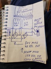
Here is what I am going to build and test.
Addresses all the issues, DC can not flow through the lower voltage diode bridge. At least on paper this will work, wish me luck.?
Daytime mode provides a boost from full PV power that has yet to be fully explored or measured yet, only thing is Mikey likes it alot a bit of magic from the power blender, boost to base voltage so PV panels operate at a higher voltage and produces more real watts of power, Awesome to see in real life.
The 42.2 voltage coil is custom added 63 turns of 12 gage wire to the ISO transformer.
Addresses all the issues, DC can not flow through the lower voltage diode bridge. At least on paper this will work, wish me luck.?
Daytime mode provides a boost from full PV power that has yet to be fully explored or measured yet, only thing is Mikey likes it alot
a bit of magic from the power blender, boost to base voltage so PV panels operate at a higher voltage and produces more real watts of power, Awesome to see in real life.The 42.2 voltage coil is custom added 63 turns of 12 gage wire to the ISO transformer.
Attachments
Last edited:
GridWorks Green Solar
Solar Innovator
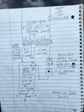
Sure two diode bridges and one custom coil are being used to make a low and high DC output voltage to the power board 42 VDC daytime and 159 VDC after hours power support 1200 plus watts availability.Can you explain individually what each of the components does?
Factory ISO transformer was name plate ratings 117 VAC input and 117 VAC output, I first added just a diode bridge to the output for about 115 VDC out to the power board results in about 600 watts of after hours power secondary seamless power availability.
Added a copper coil to the toroidal transformer of 63 turns for 42.2 volts, with the configuration in the drawing it will provide two DC voltages 42 and 159 VDC, it is pure luck that the power blender reaction occurs at 42 volts DC and the custom wound coil ended up 42.2 volts.
Would be foolish not to test it this way, excited to see what happens next?
GridWorks Green Solar
Solar Innovator
8 FETs board suffered 2 or more damaged FETs during a first ever full sun low load CPU shutdown ended with a pop noise from the inverter.
I will repost start up and shut down instructions here :
Safe Sequence to power down the system in full sun, first open the PV switches and fuses to drain the system energy, next turn off the ISO secondary transformer and last after a few seconds later turn off CPU power.
Only rule for power up is CPU is the last to turn on in the sequence, never swap cords or configuration once the unit has been started you may surge the system.
Number one rule don't mess with the configuration of system that is up and running just today accidentally turned off ISO and cause havoc, no damage done.
Had I followed the rule for shutdown this FET damage never would have happened.
6 years old factory power board will temporarily replace the broken board, CPU initially testing good on bad board.
Dual 2000 watt board headed for final bench testing and reinstall. Two or more hours of work on ISO transformer to get dual voltages working.
Excited as this should be the perfect fix for several remaining items.
Last edited:
GridWorks Green Solar
Solar Innovator
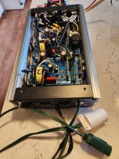
Passed final bench testing, before the cover goes on #1 New kit board 2000 watt, #2 Six year old factory board 2000 watt.
Example of a factory board in a normal inverter case. Tricky but I also did a good job. This board has been reinstalled at least 4 times now.
8FET boards are the strongest by 8% but in my personal opinion the chances for them to get out of sync and short out is much higher than the 4 FET version. Only run CPUs at 16-18 on 8FET units and always use safe shutdown proceedure.
More to come soon
ISO transformer is being a pain, I will win finally seeing 42 VDC, my drawing is not the same as factory assembled unit but just a matter of time till we get on the same page.
Attachments
Last edited:
GridWorks Green Solar
Solar Innovator
ISO transformer still on the bench and still needs the diode bridge mounted to the case and reassembled, but it works works exactly as planned ? taking a break now, should easily be ready for sun up tomorrow?
Sun sensor and time will control the secondary ISO transformer as :
Off = Solar powered only.?
Low= Boosted solar power
Hi= Full power boosted secondary power.
Fine tuning the solar sensor is next and much testing of the good things this system does now.
Sun sensor and time will control the secondary ISO transformer as :
Off = Solar powered only.?
Low= Boosted solar power
Hi= Full power boosted secondary power.
Fine tuning the solar sensor is next and much testing of the good things this system does now.
Last edited:
GridWorks Green Solar
Solar Innovator
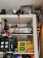
Up and running just before dark, system running in full after hours mode and both power boards are running normally.
Slow testing will resume tomorrow, just super happy to have it back working, Now running in the totally new configuration and so far so good?
Will push the limits one time during full sun conditions to see if I really am getting boosted PV power, Looking for a larger PV amp draw and also at least one night time heavy usage test.
Good news back on the old solar system, if grid power goes down I have several hours backup before I get out a generator or just using available solar.
PV= 180VDC normal.
ISO High= 160VDC after hours secondary 1200 watts.
ISO Low = 42 VDC day time PV blender boosted voltage.
ISO off= Forced solar only operation.
Attachments
Last edited:
GridWorks Green Solar
Solar Innovator
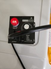
Not using the new adjustment speed controller for anything now, not compatible with the solar power systems, would call it a cheap piece of crap but it did allow me to probe the operation of the natural power blender, puts out the most AC noise of any electronic device I have ever seen before.
See you tomorrow.
See you tomorrow.
GridWorks Green Solar
Solar Innovator
Early morning, think about the original 115 VDC ISO support mode 600watt secondary, worked well for passing clouds and allows full PV to 100% stop the flow of secondary power.
Need the new ISO160 VDC secondary voltage to be variable and keyed to sun intensity for absolute perfection of operation, solar sensor about to get one heck of an upgrade, not just on/off but variable for best operation in any light condition.
Going to make this a deluxe feature so the power system is always in the right mode at the right time. Hope to get it done with out using a CPU/Computer.
On second thought a CPU that would consider system load and sun intensity and make the proper ISO voltage adjustments would be the ultimate, obviously more work ahead ?
Looking like a full rainy day, not going to set any PV records today, so I will start working on the new variable DC sun sensor.
Last edited:
GridWorks Green Solar
Solar Innovator
At 1120 watts of secondary power pull the 6 year old power board FETs faulted.
Not too happy about that but here is what I am going to do officially call after hours secondary power usage is 1000 watts maximum and replacement of the bad board with a brand new factory 1000 watt board.
Need more of the newest FETs to keep up this type of testing, hate damaging units but it is good to know your real world limitations. As it stands right now out of a maximum 10 amps secondary usage is 7.3 amps max and actual full sun PV amps is 8.3 max, recent test results say I can go higher but on the other hand I seriously can't afford max power testing.
More to come
Cut all the FETs off all the non functional boards and testing for bad, appears lost two of the 40N65 FETs on the 8 FET modified factory super board.
13 good 40N60 FETs, 6 found shorted/bad in this batch.
Good news it appears I have plenty of good parts to restore operation on the nicest boards, the to do list just got longer.
Still have 2 new factory 1000watt boards, one old 2000 watt with the large heat sinks that runs great still, 6 years-old factory board should be a fairly simple repair, and the 8 FETs board looks promising CPUs all appear working still.
New 2000 watt kit board was still running when I pulled the switches on PV and ISO power.
Have decided to fix the 6year old factory board with 4 of the new type FETs reused from the 8FET unit and populate the 8FET unit with 40N60 FETs to restore operation.
Last edited:
GridWorks Green Solar
Solar Innovator
Replaced a 10 amp glass fuse on the ISO transformer, dumped 6 year old power board on the repair bench for new FETs and restored operation on the single 2000 watt New kit board that is proving itself to be the best so far in reliability 40N65 FETs ?
Wife suggested a separate system to do load testing of the power boards.
System in Hi ISO full secondary mode right now, during high loads test earlier today the system still pulled a couple amps from PV even in rainy conditions very little sun day.
Wife suggested a separate system to do load testing of the power boards.
System in Hi ISO full secondary mode right now, during high loads test earlier today the system still pulled a couple amps from PV even in rainy conditions very little sun day.
Attachments
Last edited:
GridWorks Green Solar
Solar Innovator
I know electronics is a dry subject, but just the things that have occurred today is making me think first why did the main ISO fuse pop 10 Amps?
The ISO has a 1000 watt face plate rating and today's full load test at 1120 watts overloaded the fuse and the resulting voltage crash killed the 6 year old power board, The other new kit board rode the crash all the way down till I turned off the PV power and survived it all, the new 40N65 FETs are impressive ?
The system will likely handle 1200 plus watts secondary power support at 160 VDC as long as you have the watts to back it all up. Today's fault guarantees 1000 watt performance, only need 800 for magic with the 120 volt mini split A/C this summer.
More later, amazing
Think putting 4 of the new 40N65 FETs on the broken factory board will pay off big time.?
Onto another big step forward here about to make this thing bullet proof to mistakes, just reset and go again no matter how hard you use or abuse it.
Last edited:
GridWorks Green Solar
Solar Innovator
Mostly cloudy day, glad to see it up and running, lots more testing, see the 42 volt boost working right now different from original testing 109 VAC to 116 VAC heavy load on boost but not seeing anything on secondary power, everything secondary is routed through the current sensor.
Need automation of the sun sensor control of the secondary ISO transformer DC output, Like I said lots more work and testing needed.?
Have wonderfully smooth control over the ISO transformer now can jump from mode to mode with no problems, just need the ISO DC output inversely controlled by sun intensity for the big win.
Attachments
Last edited:
GridWorks Green Solar
Solar Innovator
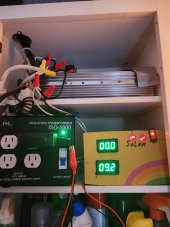
OK everyone I have the $30 220volt AC voltage adjustment in line with the wire connection to the top of the ISO circuit breaker seen in the pictures.
Provides infinite control of secondary DC power and a full control of the power blender, passing clouds today the system is making the correct decision on power usage, inexpensive and it works very well.?
The ISO transformer has been modified with 63 turns coil on the secondary to increase the maximum output voltage to 160 VDC through a diode bridge.
I will continue research on sun control but this initial step has me smiling.
I will provide a new ISO transformer diagram of how to make this work, this will be the lowest cost solution, the next and all to follow will be much more complex and expensive.
Attachments

Last edited:
GridWorks Green Solar
Solar Innovator
With the new FETs 40N65 anything is possible with this system now, but the system will falter if system load exceeds PV input, you will just need to restart the CPU and go again on the next solar day/event.Can I use this without a secondary power source without burning it up?
Years ago I was running these boards for daily full sun only daytime usage with little or no problems, have recently seen the new FETs servive a full hard voltage crash with no lasting effects twice now!, the boards are tough if you follow the rules.
GridWorks Green Solar
Solar Innovator
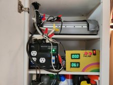
Update for new secondary ISO transformer upgrade, solved all the system problems just wish the adjustment control itself was of better quality, soldering it into the circuit would likely improve it's performance.
Not finished with adding deluxe features to the power board system but as of increasing the after hours secondary power to an adjustable 160 VDC at this point calling the basic system plan done.
Just assemble to high standards and one knob will customize your power system.?
Power blender will keep you happy ?
Attachments
Similar threads
- Replies
- 4
- Views
- 388
- Replies
- 9
- Views
- 414
- Replies
- 1
- Views
- 205
- Replies
- 24
- Views
- 1K