diy solar

diy solar

New no battery pure sine wave solar power system with smart switchers.

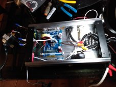
I am surprised someone hasn't asked about the large capacitors in the 2000 watt unit and why that they don't appear on any drawings.
Answer they are dangerous but add considerable kick to motor starting, extra precautions to discharge them before working on the unit is required.

You can talk to me about anything to do with electrical/solar/3D printing and industrial plastic injection molding, made car dash parts for years giant electrical molding machines with robots, production and maintenance.

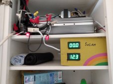
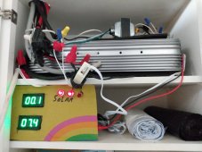
These no maintenance, fully automatic solar power systems could make a real difference in the upcoming green transition.

Good day ?
 
At sunset today I am going to do several updates on the 2000 watt system, second 10 amp safety fuse on the secondary input, replacement of the diode bridge and install isolation heat transfer pad under diode bridge (picked up a hum in a part that should not hum) have a bad connection/diode something is a miss, also going to add wires for indicator lights display.
Also will correct the current sensors to 10 turns each and correct the direction of flow.?

Got a taste of full solar.?

Just verified that both 180VDC PV inputs are working properly and ran a heater 750 watts and house lights as a real amp draw test 1 full hour, because of the hum noise I disconnected the secondary 120 volt input till the big upgrade tonight.
Honestly think the wires need to be soldered directly to the diode bridge and blocking diodes, crimp connectors seem to be nothing but trouble in the dual input section.?
 

Attachments

  • IMG_20221116_141818076.jpg
    IMG_20221116_141818076.jpg
    193 KB · Views: 5
Last edited:
Need a day of slow bench testing to go forward, upgrades completed except for wires for indicator lights.
Everything was working smooth and normal but we smelled something electrical getting hot, immediately turned it off like I said back to the bench for testing, baby steps till I understand exactly what is going on with the 120 VAC secondary input.

Maybe nothing but speculation leads to bias issue between metal bottom of diode bridge and the case the FETs are mounted to, unit has run smooth for three days before the noise. (Sounded like a transformer hum)?

(Later testing showed a damaged diode bridge from static discharge caused by a input feed bias from a grounded source) any hum/noise from a diode bridge is a faulty connection or loss of a diode due to damage)

Damaged the red neon that was mounted to the case during install, pray that was source of the smell an overheating resistor.?

Good morning 6:20 AM, it was the dropping resistor for the fans that caused the electrical burn smell (Whew), after bench and 50% load testing I have returned the unit back to operation ready for sun up?

Indicator lights will have to wait a bit, Digital current sensors are much more sensitive now.

Eliminated many crimp connectors from the dual DC input module.
Used isolation heat transfer pads and thermal paste under the diode bridge, think I really fixed it this time.?
 
Last edited:
The current sensors are 100 amp each, the PV array is fused 5amp + 5amp for a max of 10 amps total input at 180 VDC, each coil has 10 turns through the sensor coil making the reading 99.99 mean 9.999 amps.
Same thing for the 120 VAC input fused on both sides at 10 amps for safety and current sensor monitoring the DC power output from the diode bridge.

Unit is ready for hopefully years of good service.

180 volts times 10 amps is 1,800 watts, discount 100 watts for the power board to maintain 122 VAC Gives a max output of 1,700 watts of pure sine power.
On the secondary 120 VAC after the diode bridge 130 volts times 10 amps fused max current equal 1,300 watts minus the same 100 watts for the power board gives you 1,200 watts of after hours power.
Moving up to 15 amp fuses on the secondary input will supply about 1,800 max watts of after hours power.

More to come, have a nice day ?
 
Last edited:
Still an hour away away from full sun, solar is winning big, may still end up using the sun sensor to disconnect secondary completely if it detects full sun.

As with most things solar if you give it a grid crutch it will use all it can instead of processing the solar input you want.
(Later testing with a ISO transformer on the secondary input fixed to zero the flow of secondary power during full sun)?

Not hard to put the sun sensor back in the system for a win win situation.

I like what I am seeing so far but increasing load raises both sides not bad but with the sun sensor will make it absolutely perfect.?
Back to testing.
 

Attachments

  • IMG_20221117_080545405.jpg
    IMG_20221117_080545405.jpg
    212.5 KB · Views: 1
Last edited:
Crap, Still have an issue with secondary 120 volt input that caused the lights to fault (made a soft pop pop pop noise and a smell) just as full sun up.
Problem only occurs when both inputs are being fully driven. One or the other work just fine.

Unplugged secondary and everything seems back to normal on straight solar, one way or another I will solve this but it may take time.
Problem seems to occur only in actual use and not when it is on bench test, Seems like a big bias issue, if anyone can point me to a solution I can sure use the help.

Seems to be attacking the diode bridge and causing a fault so large as to discharge the high voltage buss.

Have a plan to go forward, remember the ISO transformer I purchased New just for this input because their may be a bias problem between the power sources or board?
Just started testing with it, found the secondary diode bridge is non functional.
Today after sunset I will replace the diode bridge with new one and resume testing tomorrow with the ISO transformer on the secondary input.?

I know what is happening here it is building up a charge like a Marx generator until it arcs across parts of the diode bridge, once again (reoccurring event on this project) arcs work like wires to short things out.
Don't understand how to drain off static charges before they become arcs in electronics. Any help?
Wonder if Meg ohm resistors across the diode bridge would help?
Only tool I know is the ISO transformer to address bias.

Some good news, Picture is of solar only, everything is turned on and system still has plenty of room for additional loads.
 

Attachments

  • IMG_20221117_103212510.jpg
    IMG_20221117_103212510.jpg
    214.1 KB · Views: 1
Last edited:
Doing research on Electro Static Discharge (ESD)

Have found ESD protected diodes for sale, so far for small logic stuff but all we need is a 15 amp diode bridge, will keep researching on the subject, see you soon.

Can only find small logic ESD protected diodes, some have great properties certified for CAN buss in car logic systems, most talk about rapidly clamping to stop static charges not sure that would be the correct approach in a power system??


As of tomorrow you can follow the live ISO testing and see how this progresses with the ISO transformer, absolutely sure an elegant solution exists for the static charge build up to avoid the ISO.
Shut down system in preparation for more upgrades tonight also looking to the future she is ugly but very reliable 1000 watts pure sine just need to figure out how to make it work properly.
Plenty of room in the top silver metallic unit for another power board.?

Waiting in the wings is the triple board 3000 watt unit for EV car charging, just one problem away from making it work.
 

Attachments

  • IMG_20221117_162437088.jpg
    IMG_20221117_162437088.jpg
    181.5 KB · Views: 2
Last edited:
Second ISO transformer did not solve the issue in fact failed quickly, I am currently at a loss to explain what is going on it works than one switch flip later a fault, have run out of time will be absent for about a week. My smart switchers have a two seconds transfer gap but they also work, will return to my deluxe switcher until I can solve the secondary fault issue. Don't power the secondary input unless you are attempting to help solve the problem or like damaging diode bridges, longest lasted three days the new one I just installed lasted only minutes.?

Passed bench test, ran for two minutes perfect, switched ISO transformer off to move a cord to new location once I turned it back on a noise from what I suspect was the diode bridge and a small glass fuse in the ISO transformer blew and that is where we currently sit, may be a phase timing problem but how it is going through the ISO transformer beats me, these 40 amp diode bridges are only being exposed to a few amps of 120 volt power.
Additional information about last evenings fault, when I switched on the ISO transformer apparently the inrush of power caused one or more FETs to fail that caused a short on the high voltage buss that took out the glass fuse on the ISO transformer.
If you start the unit from the CPU it does a soft start that might have helped in this situation.

See you soon ?
 
Last edited:
When I get the time I will repair everything and test again, Good news it may still work with the ISO transformer, just need to proceed slowly until I win this.?

Right now it looks like a new fuse holder and fuse for the ISO transformer and one or more FETs, still have 12 new FETs in the bag.

Still have today and all day tomorrow, Just repaired the ISO new 10 amp standard fast blow fuse and holder, disconnected and removed fuses from the PV arrays, next pull the unit off the shelf and get it on the repair bench.

So close but yet so far away from what I need, Good Day all.
 
Last edited:
Accidentally discovery about how the power boards work, this latest FET fail is suppling DC power out the output of the power board.
Not the first time I have seen this also in another brand power inverter when the output FETs failed.

Last FET failure came with an approximate 550 watt load seemingly going to no where, I now know exactly where this power is going and it is good news from a safety standpoint.
The main Isolation transformer is directly connected to the power board output this does two things first puts the power into a fused loop (550 watts) and secondly completely blocks the DC power flow. (Law of nature DC cannot pass through a AC transformer) worst case scenario contained in a fused metal box.?

Seriously glass fuse everything at 15 amps or less it is important to safety and anything over 24 Volts needs to be mounted in a metal box/case, Cheap inverters go bad all the time expensive ones last longer, never intended to ever overload the 2000 watt power board ever again but did not think about a surge taking out FETs.

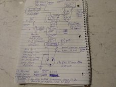
⚠️ New rule when restarting the power board systems always power up the CPU last . System soft start.⚠️

Good news diode bridge and dual input test good, ISO transformer good, just need to repair or replace the power board.?

Replaced all eight FETs on the 2000 watt board but still no go from the CPU, will fix it later.
Drafting the 5 years old 1000 watt board into full service to keep things progressing forward.
Just passed bench test and ready for reinstall will be ready for sun up tomorrow.
See picture ?
 

Attachments

  • IMG_20221118_170234723.jpg
    IMG_20221118_170234723.jpg
    230.6 KB · Views: 5
Last edited:
Ready for sun up, three indicator lamps solar input won't be on till sun up, on aux power power right now running smooth.
Running second ISO transformer this time and turned on the CPU last for the soft start power up.?
 

Attachments

  • IMG_20221118_175701926.jpg
    IMG_20221118_175701926.jpg
    185.4 KB · Views: 4
Just occurred to me the CPU power feed and the secondary feed need to be from the same source so you always get a soft start upon power return, mine will be powered from the older solar gopower system.

Only one more day to test then about a week off.

Need full sun tomorrow.

More long term testing is needed but I am 99% sure that anything feeding the power board from a grounded or negative ground power system will require a isolation transformer to function normally.
If you don't follow this rule the power board or diode bridge will build a static charge to the point of eating itself.
Also just occurred to me why the PV panels don't explode the power board only because the + and - neither one are bonded to ground or the solar panel frame.
(Wow moment)

Indicator lights third one is solar high voltage ?
 

Attachments

  • IMG_20221118_203404780.jpg
    IMG_20221118_203404780.jpg
    236.6 KB · Views: 4
Last edited:
Hopefully the final power system diagram, disregard all previous drawings.?
Anything hooked to this system from a grounded or negative ground power source needs an Isolation transformer, the power board or diode bridge will be seriously damaged as a result of not following this rule.

Will be tested both ways but expect final version will incorporate the sun sensor to turn off secondary power when it detects full sun.?

Working perfect,sun sensor not needed.✅

Isolation transformer on secondary feed fixes to zero the power used during full sun, almost hard to believe won't claim victory till I see it return to secondary power later today.simply amazing.
During this day the neon lamp has faded to off for 180VDC PV input it was only rated for 120VAC and I knew from past experiences it would stop working early.
Getting near the end of a perfect solar day and test. See you later ?
 

Attachments

  • IMG_20221119_061015703.jpg
    IMG_20221119_061015703.jpg
    221.1 KB · Views: 3
  • IMG_20221119_084207061.jpg
    IMG_20221119_084207061.jpg
    231.9 KB · Views: 3
Last edited:
Clouds moved in for ending of this solar day, seamless transition to secondary has begun. I will get another photo near finished.
Claiming success, have It working beyond expectations.?

One week away, unit will be switched off late tonight, more testing and improvements later.?

Test of normal day, will slowly load the system to maximize use.

Right now the PV indicator needs to be correctly replaced and the cooling fans are running a bit fast for my preference, other than that flawless performance today.?

What makes it work is the second ISO transformer runs smooth real smooth. Next pic solar fading away.last picture sunset.
 

Attachments

  • IMG_20221119_161738196.jpg
    IMG_20221119_161738196.jpg
    188.9 KB · Views: 3
  • IMG_20221119_165037888.jpg
    IMG_20221119_165037888.jpg
    201.9 KB · Views: 3
  • IMG_20221119_171549004.jpg
    IMG_20221119_171549004.jpg
    186.5 KB · Views: 3
Last edited:
Three pictures, all primary solar, first light this morning, full secondary power.
One good solar day.?

Shut down system, turned off Isolation transformer and let power board drain the caps, turned off CPU and fan power, opened PV switchs and removed fuses for a cold park.
Plugged house lights/fans into a 15 amp grid powered outlet.

Will resume testing in about a week. Happy Holidays all.
 

Attachments

  • IMG_20221119_084207061.jpg
    IMG_20221119_084207061.jpg
    231.9 KB · Views: 2
  • IMG_20221119_070455171.jpg
    IMG_20221119_070455171.jpg
    204.3 KB · Views: 2
  • IMG_20221118_175701926.jpg
    IMG_20221118_175701926.jpg
    185.4 KB · Views: 2
Last edited:
In another state for the Holiday, ask questions, tell others, get your own copy of the latest drawing.

What has happened in the past few days, I now have a full understanding of the strong bias that damages FET driven inverters and power boards, also much learned about the inner workings and what can go wrong when one or more FETs fail.

Have ruined more than a dozen standard inverters and 6 power boards over the past 7 years because of not fully understanding the strong negative ground bias problem, Understanding the problem fully not only got the new invention working perfectly but anyone that understands this fully will not blow up a standard inverter or FET driven power board anymore.

Simply put standard inverters need a Isolation transformer to stop the bias and correct the power for a normal neutral and ground.

Second anything you connect to a standard inverter or FET driven power board from a grounded or negative ground power system must have an Isolation transformer between, If you don't a static charge will build up in the power board or associated input devices and cause serious damage to the electrical parts of the system.

This system is efficient and can provide a serious solar punch even on a gray day, what I witnessed yesterday (a good solar day) was simply amazing, I could hardly believe it when secondary power was 100 % stopped by the PV input.
The Isolation transformer fixed the power usage from the secondary input.

This maintenance free system works better than expected and will definitely be cost effective in multiple ways, hard to express how well it works, makes the most out of less than perfect conditions, actual rain, snow or darkness is what it takes to shut down solar production, Will seamlessly transfer to the secondary power input of your choice when solar is not enough.?

Need to remove/redo about half of equipment for the old solar system and shift portions of the old systems output load over to the new seamless system, when ready a test is coming for the side by side fridge, getting the 2000 watt pure sine board working again is part of this plan.
After that a push for a 3000 watt capable unit for EV car charging will be the focus. Can temporarily run three sets of 9 panels for 2500 watts on a 3000 watt capable pure sine board.?
 
Last edited:
If you closely review pages 6 and 7 of this thread you will see how I solved the puzzle.
The (WOW) moment was the full understanding of how the PV panels can power the pure sine wave power board directly and never cause any issues.
This power system should probably be called the ISO power system even in off grid although the transformer is not required it is recommended to protect the power board from connecting to a grounded device also corrects the 120 VAC pure sine power output for a standard neutral and ground like grid power.

Do everything up to code, and fuse everything at recommend levels, recommend 250 volt fast blow glass fuses. Always safety first.?

Good day all.?
 
Last edited:
A fun thought experiment with my new knowledge.

Have you seen the new pickup trucks with the inverter in the back for powering tools and so forth?

Ok because the battery,inverter and alternator are all sitting on four rubber tires you can get away with a lot including power up a grounded peice of equipment.

Let's say the battery is dying on the truck and you want to boost it up with a grid powered battery charger, at the moment you connect the charger to the battery you have just introduced two grounded connections directly to the inverter power board. (First the netural side of the battery charger and the second the grounded peice of equipment) chances of the inverter serviving this situation is between slim and none.

To prevent this situation you need a Isolation transformer on the input of the battery charger from grid power.

Wish I had figured this out long ago ?
 
Last edited:
Good morning all

New idea but it will be put off till later must resolve other issues first.

Noticed over the years and strongly reminded just recently of how power surges damage the FETs in inverter systems. Examples: Cooking with an electric skillet for 20 minutes and the inverter failed when the thermostat clicked back on, turning on the ISO transformer without restarting the CPU for a system soft start, surges from motor starting, and generally additional large loads on a system that is already up and running.

Coming up with a way to sync and blend output power from multiple power boards could make these new power systems bullet proof.

Most inverters brag on the product labels about how much surge the inverter can handle, I have found through real world testing most of this is bogus, even a modest surge can immediately damage the FETs shorting out the high voltage buss and causing serious damage to the FETs and CPU of the unit.

See you soon.?
 
Last edited:
Good morning

When I return home I have two paths forward with the project, first involves ordering CPU parts from China and restoring individual power boards that were damaged during the testing of the dual DC input module or figure out how to sync the individual power boards to one CPU for a quantum leap forward.

I currently have only one 1000 watt pure sine power board that works perfectly with the seamless power blending and a second 1000 watt that has the dual DC power header and is now ready to be used.

If you have learned anything about me you know the path I am about to embark on, the sky is the limit if I can sync these power boards at the CPU level.

I have already made one attempt to sync boards but failed either the 2000 watt board CPU was damaged before the experiment or the act of combining the power boards killed the CPU.

Next experiment will go as follows, new power board will be configured and bench tested, will add the jumpers for the sync of the secondary board and test again.

Not sure yet if the secondary board will be a 1000 or 2000 watt, I will keep you posted on the testing.
Ultimate goal is synced 3000 watt combo unit for the house and another 3000 watt unit for EV car charging.?
 
Last edited:
Back
Top