GridWorks Green Solar
Solar Innovator
Good morning
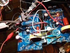
Thinking about how to command the secondary power board from the primary CPU, the center four FETs is all that is needed to produce pure sine power, the outermost four FETs are directly tied to the inner four so you can easily double the output, in the previous attempt to sync I used the four FET trigger signals and a the CPU trace marked (gnd) (total 5 wires) on the CPU to copy the signal to the other power board.
For what ever reason the first attempt did not work, in the early days of computing we would double the RAM on our computers by stacking the chips on top of one another and soldering all but one pin that went to another controller chip.
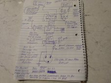
I think my next attempt will be (12 wires) to duplicate the center four FETs to the secondary board (3 wires for each FET) may also need to run the CPU (gnd) wire to the secondary board.
Wish me luck ? I really need this to work.?
Thinking about how to command the secondary power board from the primary CPU, the center four FETs is all that is needed to produce pure sine power, the outermost four FETs are directly tied to the inner four so you can easily double the output, in the previous attempt to sync I used the four FET trigger signals and a the CPU trace marked (gnd) (total 5 wires) on the CPU to copy the signal to the other power board.
For what ever reason the first attempt did not work, in the early days of computing we would double the RAM on our computers by stacking the chips on top of one another and soldering all but one pin that went to another controller chip.
I think my next attempt will be (12 wires) to duplicate the center four FETs to the secondary board (3 wires for each FET) may also need to run the CPU (gnd) wire to the secondary board.
Wish me luck ? I really need this to work.?
Last edited:

 and for soft restarts of the system the CPU should be feeding off the secondary power input