diy solar

diy solar

New set up. Spark at connectors?

Vega

New Member
Joined
Feb 14, 2020
Messages
42
Hey

So I just finished setting up this li-ion battery from repurposed cells.
It's my first one of some scale (7S10P 29.4V 33AmpH), and it seems to work well.

Now for the first time I hooked it up to my solar panels.
They are each 50w, so I put them in series to give 24v.

It looks as if everything worked well (as of now I only tried them in dim indoor light).

My question has to do with the connecting of the cables.

I remember from a video on youtube from Will Prowse that you should give a spark to one of the terminals before connecting them. In my case however I got XT90s and XT60s, so there's no chance for that in my set-up.

When I connected them now indoors (solar panels facing down) there was a small spark at the connectors from charge port of the solar charger to the battery. Afterwards I turned the solar panels facing upwards, and when I connected the inverter to the discharge/output port-- again a spark. I couldn't see it, I only heard it. It left a small burn mark on the connecter. It seems insignificant -- do damage. Just a mark. But I was wondering if I am doing something wrong here. Any tips?
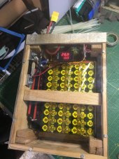
236414500_379762676867111_3563039300135205811_n.jpg236964848_551728062645990_3662803944326011871_n.jpg


Cheers
 
Hey

So I just finished setting up this li-ion battery from repurposed cells.
It's my first one of some scale (7S10P 29.4V 33AmpH), and it seems to work well.

Now for the first time I hooked it up to my solar panels.
They are each 50w, so I put them in series to give 24v.

It looks as if everything worked well (as of now I only tried them in dim indoor light).

My question has to do with the connecting of the cables.

I remember from a video on youtube from Will Prowse that you should give a spark to one of the terminals before connecting them. In my case however I got XT90s and XT60s, so there's no chance for that in my set-up.

When I connected them now indoors (solar panels facing down) there was a small spark at the connectors from charge port of the solar charger to the battery. Afterwards I turned the solar panels facing upwards, and when I connected the inverter to the discharge/output port-- again a spark. I couldn't see it, I only heard it. It left a small burn mark on the connecter. It seems insignificant -- do damage. Just a mark. But I was wondering if I am doing something wrong here. Any tips?
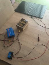
View attachment 59967View attachment 59968


Cheers


Before you connect the 2nd terminal into the inverter put a big resistor (or some lightbulbs) between the terminal and cable, to charge the capacitors.

Check this video from Will:
 
Hey

So I just finished setting up this li-ion battery from repurposed cells.
It's my first one of some scale (7S10P 29.4V 33AmpH), and it seems to work well.

Now for the first time I hooked it up to my solar panels.
They are each 50w, so I put them in series to give 24v.

It looks as if everything worked well (as of now I only tried them in dim indoor light).

My question has to do with the connecting of the cables.

I remember from a video on youtube from Will Prowse that you should give a spark to one of the terminals before connecting them. In my case however I got XT90s and XT60s, so there's no chance for that in my set-up.

When I connected them now indoors (solar panels facing down) there was a small spark at the connectors from charge port of the solar charger to the battery. Afterwards I turned the solar panels facing upwards, and when I connected the inverter to the discharge/output port-- again a spark. I couldn't see it, I only heard it. It left a small burn mark on the connecter. It seems insignificant -- do damage. Just a mark. But I was wondering if I am doing something wrong here. Any tips?
View attachment 59967View attachment 59968


Cheers
The sparks are caused by inrush current to capacitors. This is usually small with charge controllers. Some inverters (with large capacitors) can cause some rather large inrush. A precharge circuit will ease the inrush. Alternatively connect everything through breakers or other disconnect switch. It won't ease the inrush, but you won't have to see/risk any sparks.
 
Alright thanks guys for the answers!
As I mentioned I'm using XT60s and XT90s, so there is no "connecting to the second terminal". But I suppose I could do this capacitor trick by sticking it into the XT90 of the discharge port, before connecting the inverter.
But regarding the solar charger then, how can I avoid the spark there -- or is that inrush so small it doesn't matter?
The general consensus seems to be it doesn't matter, but you can do the same thing with a resistor to precharge its capacitors, too.
 
The general consensus seems to be it doesn't matter, but you can do the same thing with a resistor to precharge its capacitors, too.
And does that matter even if the solar panels are up with full sun or not?

I can't seem to find these resistors like in the video, here locally. Someone mentioned something about a string of lights as alternative-- how would that set up look like? Any clues?

Cheers!
 
Alright check it out, nice -- very simple eh! It's a bit hard to tell from the photo but I supposed that's just soldered on there. Do I need any particular specs for that light bulb?
 
And does that matter even if the solar panels are up with full sun or not?

I can't seem to find these resistors like in the video, here locally. Someone mentioned something about a string of lights as alternative-- how would that set up look like? Any clues?

Cheers!
before you connect the solar panels to the controller, connect the controller to the battery, and configure whatever settings you need to configure. then connect panels.
 
Just FYI:
100W 220VAC incandescent lamp will have Hot resistance of about 489 Ohms, the cold resistance will be about 15 times less, so it will be about 32 Ohms which should be fine for limiting the inrush current, as the current starts flowing the filament will heat up and so the resistance of the filament will rise up.

50W 12V car lamp will have hot resistance of about 3 Ohms, the cold resistance will about 0.2 Ohms.
 
Last edited:
Back
Top