Hey all,
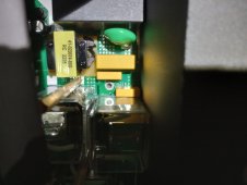
I recently got my two 6500ex's from signature solar, the build date on them is 10/2022. I assumed the bonding screws were in place from reading this forum and contacted signature solar for permission to remove them, they gave me permission, and I went ahead and opened them up, and the bonding screws were not there! I wish I knew about this before so I didn't have to open the case.
This is great and how it should be shipped, thank you EG4!