So basically an amp clamp on AC in and another on the inverter right?
Am I correct to assume generator amps and charging amps displayed in dashboard are reported from the internal AC input CT and inverter CT sensors?
View attachment 147846
Since DC current shunts are expensive and take up space, the battery current is often calculated from battery voltage, inverter AC voltage and AC current, with a derating for inverter efficiency based on absolute power level. I believe Quattro offers an optionally purchased battery monitor addition that does actually measure battery current.
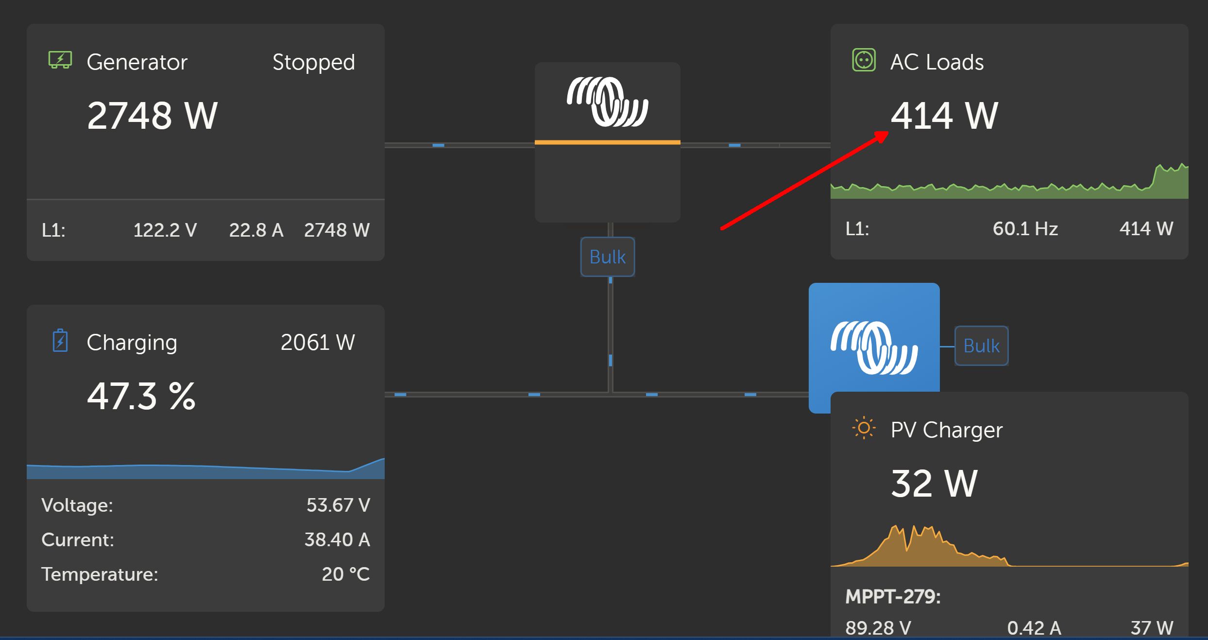
You can usually tell it is calculated from AC power when charging AC input current remains relatively constant but charging bulk DC battery current reading drops a bit as battery voltage rises during charging. Inverter AC input current is actually doing the charging DC bulk current regulation.
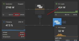
In the picture, 2061 watts is calculated net charging power after inverter AC CT sensor reading x AC input voltage x inverter efficiency.
The 2061 watts charging is with efficiency derating, for that power level it is likely about 90-92%. That would mean actual input AC current to inverter is about 2290 watts / 122.2v =18.74 amp rms.
The VRM Dashboard has an issue as to what it should present. If it reports efficiency corrected number for charging current, which it should, there is going to be a discrepancy in the AC input, AC output, and charging power summation when inverter efficiency is taken out. They likely don't want to clearly expose there is over 200 watts being pissed away in efficiency loss.
In this case, the efficiency loss, about 229 watts, is missing from the power summations. At least that would take the unaccounted for 414 watts AC output power down to 414w - 229w = 185 watts. That would be 185w/122.2vac = 1.5 amps AC of measurement error.
That is a believable error for the 22.8 A absolute AC input CT amperage measurement, minus the 18.7 amps absolute inverter AC input CT amperage measurement.
Some of the approximate 1.5 amp error is due to AC input CT sensor reading, some of 1.5 amp error is due to inverter AC input CT sensor reading. There is also a little contribution due to AC voltage reading accuracy.
There is still some power unaccounted for to run the controller electronics, display, and pass-through relay coil. That summation is probably in the ballpark of 5 watts. Also, although pretty good, the charging AC power factor is about 0.90-0.92 which may add some error in power calculations.
The charging AC current profile does follow a sinewave shape fairly well due to PWM switching, but the charging AC sinewave current does drop out for a small time period gap around zero crossings of sinewave. This causes some error in CT sensor rms current reading. CT sensor is not to be blamed for this AC current shape distortion.


") Thank you.
Thank you.