diy solar

diy solar

'Non Growatt' Eastron SDM230 Modbus V2 with Growatt SPH3600

Capt Kitch

New Member
Joined
Jan 3, 2023
Messages
23
Location
Glasgow
Hi, does anyone know if the Eastron SDM230 Modbus V2 bought from the likes of Amazon (from this thread:-https://diysolarforum.com/threads/growatt-sph-and-power-import-control-from-grid.39897/) will still work with the Growatt SPH series (with the address change to 002 if required) or as stated by another forum member do you have to get Growatt's own version to ensure it works?

I can see a lot of members have bought the aftermarket version and it works but has something changed recently:-

Quote "I had a reply from Growatt support. If you don't buy the smart meter at Growatt, it will not work because Growatt re-write the smart meter registers.
FYI: Growatt smart meters are now CHNT, it looks like they don't use Eastron anymore. Anyway, if you want a smart meter that works with the Growatt inverter, it NEEDS to be in a Growatt karton box. (if not in a Growatt box, it will not work)" or is this Growatt trying to make you buy their own?
 
 
I have now bought the Eastron SDM 230 V2 from Amazon and connected it up but the residual grid import power has increased to 400-500w all the time as opposed to 100w (ish) with the CT clamp! It is communicating with the inverter as the telephone symbol is there - but it is there with the address set to either 001 or 002!

Could anyone who has done this please tell me what the correct settings of the Eastron should be i.e. address/baud rate/parity etc. so I can get to the bottom of this?

Thanks.
 
I have now bought the Eastron SDM 230 V2 from Amazon and connected it up but the residual grid import power has increased to 400-500w all the time as opposed to 100w (ish) with the CT clamp! It is communicating with the inverter as the telephone symbol is there - but it is there with the address set to either 001 or 002!
OOpps, that's annoying. I assume you can switch back to the CT? Sorry for the worse performance and thanks for letting us know.
Sorry if this is obvious but I assume you connected the meter the right way round, in the tails to the consumer unit?

Cheers...
 
Yes - all wired up correctly. Just puzzled as why I get the telephone ? symbol when the address set to either 001 or 002. This would suggest that the communication is there in both cases but which is correct? The baud rate is correct at 9600 as changing this stops the communication. Was using the existing RJ45 cable for the CT to connect to the inverter but have noticed that the wire colours in the extension cables don't match Growatt's so will check if something is incorrect there - maybe the wires are transposed. Have reverted back to the CT Clamp at the moment until I can do some more checking - which is not ideal as I have discovered that the CT Clamp ferrite core is cracked across one of the corners so can't be working properly either!
 
I did do the same as you initially and thought I was on to a winner as it indicated communication straight away as well......
Hi, I see you are in the UK? Can I ask how you got it wired into the tails as the main fuse needs removing and re-sealing. My previous supplier was totally clueless about this and when I eventually got them to understand what I wanted, they quoted £250 to test and re-seal. I have now moved to Octopus and hope they understand a bit better!
 
I fitted it into the main consumer unit as I could create space on the mounting rail due to fitting a new consumer unit a few months ago. I got Octopus to fit a new main isolator after the main meter as there wasn't one originally and I couldn't therefore change the consumer unit myself. So power on mine goes:- main fuse - main meter - new isolator - consumer unit isolator - Eastron Meter - consumer unit/solar input. It was tight routing new cables to it but saved mounting in a separate box.
 
I fitted it into the main consumer unit as I could create space on the mounting rail
OK, thanks for the info. I have some comments and questions...

a) The jokers who fitted my solar PV and battery installed the CT in the consumer unit. The installed it the wrong way round so for three days the battery continuously charged from the supply, and discharged (and used 30-40 kWh per day!). I eventually realised and switched off the battery, and they came back and turned the CT round so that stopped that issue.

b) However the readings from the CT in the consumer unit were very inaccurate (1 kWh consumption when 100W used, for example).
I moved the CT to the external meter cabinet and fitted all-new Cat5e from the CT to the invertor - which solved the inaccuracy. I suspect the CT was seeing a lot of noise in the consumer unit (But I still 'leak' 100w per hour in from the supply, hence the SDM230).

c) That brings me to your SDM230 problem - I wonder if it is the same as my CT in the consumer unit - there is just too much noise in there, and it might work properly in an external, separate enclosure?

d) That's how I have installed my SDM230 - in the external meter box, on its own (of course, I don't have an isolator like you so it is not fully connected yet...)

e) Do you mind me asking how much they charged to fit the extra isolator please?

Just a thought?
 
Not sure if the Eastron Meter would be subject to 'noise as such' as it is directly in the live/neutral line and there is nothing in the instructions to say it should be remote from other items. The isolator was free! I needed to upgrade the main consumer unit to modern standards to fit an EV charger. I have been on Octopus Go Faster for over a year now and they had assumed there was one fitted as part of getting that tarrif for an EV I said it wasn't and they came and did it - also allowed me to verify that the main fuse was 100A for the future solar install.
 
My CT is on the link between the meter and the new isolator and therefore outside the consumer unit but still generally shows 100w grid input
 
My CT is on the link between the meter and the new isolator and therefore outside the consumer unit but still generally shows 100w grid input
OK, as I said when my CT was in the consumer unit it sometimes read 1kW when 100W was being drawn. The CT is ovbiously a closed (split) ferrite so theoretically should not pick up from anywhere else when fitted, but it certainly was - and was *nearly* resolved when I moved it (as I said get around 100W grid input). I agree it's unlikely but maybe the meter is picking up noise from somewhere...

I have moved to Octopus just 10 days ago and they've been very efficient about it - the Smart Meter IHD continued working and they put me on the 'Intelligent Octopus' tariff immediately (6 hours overnight at 10p / kWh) for charging my EV.

I unfortunately have a modern CU but maybe I can get them to install an isolator as I might want to install a level 2 charger for my EV ...
 
I am going to move the Eastron into a separate 2 gang box (couple of quid from Screwfix), outside of the consumer unit, check the lan cable wiring, and try again from there. Can't be any worse and worth a try.

They should be able to install a seperate isolator as it is the only way to safely allow modification to the CU. Even if you turn off the CU isolator it is still live into the unit and not completely disconnected. I upgraded mine as it was from 1980's, plastic,not enough spare ways, non split load, wrong 'type' of RCD for EV use (type A needed) and needed new different type of MCBs for the EV (type C). Cost about £110 to buy.
 
I am going to move the Eastron into a separate 2 gang box (couple of quid from Screwfix)
Hi, good luck! I hope I haven't misled you - but at least it is not costing you much. Maybe you can wire it up temporarily to test it and then fit it properly if it works? Be very interested to hear how you get on. All the best...

My CU is from 2008, split load with two RCDs so doesn't need updating... Currently I just use the supplied level 1 charger for my EV...
 
In the process of clearing space on the wall by the consumer unit to put the Eastron in its own unit I noticed a 'buzzing sound' coming from the CT clamp.

As mentioned earlier this has been broken - possibly before fitting or during fitting - it is a ferrite core in a 'c' shape with a 'l' piece across the arms when snapped shut over the meter tail. The sense coil is over one of the 'c' arms.

Mine was broken across the corner of the 'c' piece and was not making a close fit anymore hence the buzzing. Managed to dissasemble and then carefully glue (thin superglue) the arm back on with the faces accurately aligned.

Replaced and taped around to keep it pressed together - and now the import current has dropped to around 50w! Irritatingly it has been like that from install and underreading the import current due to the poor fit/break!

Shows the CT clamp is inaccurate!

Will keep you posted on the meter install.
 
I noticed a 'buzzing sound' coming from the CT clamp.
Interesting... Back in July when the clowns first installed our solar PV and battery (since then I've moved the CT and re-wired quite a bit of the system) the CT was in the CU and there was a loud buzz all of the first day! That wore off and obviously wasn't an issue when I moved the CT to the external meter box.

However, the CT centre hole is a bit too small for the 25mm2 cable so I've tried to force it shut with cable ties, but am not sure how well the two ferrite halves are making contact. Maybe as you've reduced the import to 50w (from 100w ??) I'll have another go - but of course, it's an interim measure (and backup) until I get the Eastron installed...

Cheers!
 
My CT Clamp centre hole is much bigger than the 25mm cable. Perhaps you have the wrong clamp? Yes - has gone down from 100-125w to 50-70w.20230226_135150.jpg
 
Some CT clamps are for 25mm live tails others for 16mmlive tails, depending on house DNO fuse holder might say 100 Amps rating but fuse inside could have 80Amps fitted by DNO or even lower 60Amps for the property.

If you have smaller tails 16mm after DNO Main meter to Isolator then connect there or just before an Henley Block to normally Split tails before House Consumer Unit to maybe 2Way Mini CU for EV charger and another for 4or 6 Way Mini CU for Solar and Batteries on their own RCBO’s

I did buy CT clamp from Amazon when connected read erratically up to 400W
and on inspection the ferrite was also broken/ cracked and replace with different make which works
My Solax X1 Boost 3.6 kW inverterwas not taken house load 250- 300 W until looking at settings to change the CT/Meter Direction from Default - Positive to
Negative and my Octopus Home Mini device
(You need to ask Octopus for one free of charge) which shows live data use for the Daty in 5mins and 30 mins in increments of 10 sec live data. So my import previously was 86kWh with the CT/Meter Default Direction- Postive.

Now last months Import was 15kWh after Chnging the CT/Meter Direction from Default to -Neagative value which is a huge improvement and saving and my batteries making a big impact on house load being taken up.

This has taken over 3 months to understand
my system when MSC installed and my import daily was registering 2-3 kWh import daily now exporting 50w on SEG to Octopus which shows the export equivalent amount.
To be honest was not that impressed with the knowledge of my installer after installation and setting up the system. He was adamant it
was “Working fine” lmao now

Maybe their is a setting available for your inverter to do the same.
 
Some CT clamps are for 25mm live tails others for 16mmlive tails
Hi, thanks for the info...

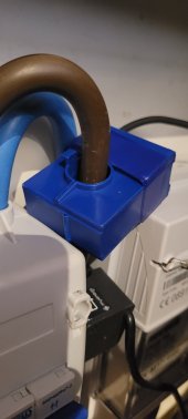
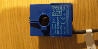
a) I have 25mm tails and the diameter of the CT is 10mm or so - the diameter of the wire is 11.5mm. Below is a picture of my CT installed - the blue is the Growatt supplied CT and the white is the CT for the immersion heater iBoost... The second photo is the CT - looking at the serial number I reckon S10 means the hole is 10mm diameter.

b) Can I ask where you got your replacement CT and if anyone has any suggestions where to maybe get one with a bigger (say 16mm diameter) hole?

c) Thanks for the info about the 'Home Mini' device - I've logged into my Octopus account and am on the waiting list for one now!

d) What's the model of your CT with the larger diameter hole, please?

Cheers!
 

Attachments

  • CT Device.png
    CT Device.png
    824.2 KB · Views: 11
  • CT.png
    CT.png
    654.6 KB · Views: 11
Last edited:
Back
Top