On a side note, one thing I don't like about my Magnum's internal charger function, is when I start the generator to charge, the inverter section automatically goes into bypass, so then the generator has to run all the normal output loads + the charger too (requires bigger generator which can meet both demands).
My most recent solution is to just use two standalone chargers to charge the batteries directly from generator, so the inverter will stay on like normal, and charge that way, alongside.
I will also be doing this with my final home 48v system too, since the MPP Solar LV6548 all-in-ones I have also must go into bypass mode in order to charge the batteries from AC input (is not able to charge while 'inverting'). So I bought 2 AIMS 120v 48v chargers to wire in, one on each leg of generator, so i can just add supplemental charging on my own circuit to the batteries.
Perhaps at worse case, you could just buy some 48v chargers and add them in and not use the AC input on the 4448 at all. Or so you can just buy some time and fix it later...
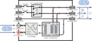
All hybrid inverters have inverter-charger connected to AC output. When AC input is detected, and before AC pass-through relay closes, the inverter is slowly brought into phase alignment and AC input voltage matching. Once this is achieved the pass-through relay closes and AC input is passed through to AC output with inverter-charger in parallel.
The difference is if hybrid inverter allows load shaving of AC input. Some low cost LF hybrid inverters and most HF hybrid inverters do not do AC input load shaving. If it does not do load shaving then AC input provides AC charging and AC output power with no control on maximum generator loading.
LF hybrid inverter are inherently bi-directional so it is very easy for them to do load shaving. HF inverters are not inherently bi-directional and have to switch forward/reverse power operating modes that takes several milliseconds to switch between. This restricts HF hybrid inverter from load shaving unless they have a large bank of high voltage storage capacitors to provide load power while battery to HV DC converter is temporarily inactive making its forward/reverse power direction switching.
On Magnum inverters, they call load shaving 'Shore Max' which is a user set limit for AC input current.
From Magnum manual:
Shore Max - This setting ensures the inverter AC loads receive the maximum current available
from the utility or generator power. When the total current used to power the AC loads and charge
the batteries begins to approach the Shore Max setting, the current that was used for charging
the batteries will automatically be reduced.
This means AC output has first priority on limited AC input current.
Usually, a LF hybrid inverter with load shaving will allow battery power to supplement AC input power to allow AC output load greater than generator capability. I am not sure if Magnum does this. Victron, Xantrex, and Outback units do allow this.
The most common issues with AC input from a generator:
1) Generator out of freq range (synchronous constant rpm generator)
2) Too much rpm wobble due to unstable generator engine governor rpm control preventing inverter from achieving phase lock (synchronous constant rpm generator). Generator sound should be smooth and constant, without any 'wah-wah' sound pitch variance. Frequency accept range limits is not the same as frequency lock wobble range. Lock for inverter requires generator frequency wobble less than about +/- 0.3 Hz around AC frequency (50 or 60 Hz).
A sudden surge load on a synchronous fixed rpm generator can cause rpm variance dip causing inverter to release from generator. This is where AC output supplementing from battery power through inverter really helps prevent generator from seeing a sudden AC output surge, like an AC motor startup. Victron takes this a step further with their dynamic load shaving where the inverter begins to supplement AC output load that starts to quickly rise before it has actually reaches the AC input current limit set by user. It backs down the supplementing by battery when AC output load settles out.
3) If inverter has AC input current limiting (load shaving), not set properly for generator power capability resulting in overloading generator. Inverter will connect to generator then quickly disconnect from generator when generator bogs down from overload. Inverter may wait some time period and try to reconnect again.
4) If inverter does not have load shaving, setting charger at a level that exceeds power capability of generator, again overloading generator.,
First thing to listen for is pass-through relay engaging indicating inverter has achieved lock on generator. Many inverters also have an indicator LED. This can take from about 10 seconds to upward of a minute or two depending how much initial frequency difference between generator and inverter.
Inverters that have two AC input options often have the AC input used primarily for grid connection set to a tighter AC input frequency range that may not cover the actual frequency of a synchronous, constant rpm generator, therefore the inverter may not lock to a generator out of the tighter frequency limit range.
For inverter-generators, the frequency and its stability is usually very good, but they can react very quickly to overload by shutting down their AC output. When using ECO mode, where rpm is reduced, sudden load increase causes output sinewave to be peak clipped until engine rpm comes up to higher rpm's to meet the higher load demand. Usually, the inverter will step up to supply the additional sudden load until inverter-generator comes up to speed, so the inverter does not release from inverter-generator.
For a LF 240/120 vac inverters that allows just a 120 vac input it is important to remember the AC input current load shaving limits is only providing half the power that a 240 vac input would supply.