shadyshabin
New Member
- Joined
- Apr 28, 2022
- Messages
- 7


Nothing jumps out as terribly wrong. But here are some observationsHey all,
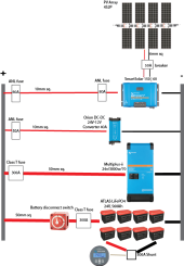
I'm after some fresh and more experienced eyes to double check for any design flaws before I spend some money! This is my first solar design for an off grid cabin.
Appreciate any feedback!
")


 diysolarforum.com
Ahh thank you for sharing what you picked up!!Nothing jumps out as terribly wrong. But here are some observations
Edit: Corrected wire gauge on the diagram.
View attachment 97619
* The wiring going to the 24-12V converter seems larger than it needs to be. With a 40A output and a 90% efficiency, it should only draw (40/2)/.9=22.2A. For a fuse I would take it down to a 30A fuse and 10AWG (6mm^2) wire.
* Every time you turn the batter disconnect switch on, there is going to be a very large spark internal to the switch because of the big capacitors on the input to the inverter. (This will happen even if the inverter is turned off). You may want to consider putting a disconnect switch with a precharge circuit on the inverter circuit. Then you should always make sure the inverter is disconnected before you turn the battery switch on.
* There is not enough detail on the battery and shunt wiring to give any comment.
* It kinda looks like you have 2 strings of 4 panels. Depending on the panels, that might (or might not) create too high of a voltage in cold weather for a 150V MPPT.
Adjusting Solar Panel Voc for temperature
When designing you solar panel system, it is important to adjust you solar panel Voc for temperature in order to ensure you do not over-voltage the PV inputs of your solar charge controller. This paper shows how to calculate the Temperature...
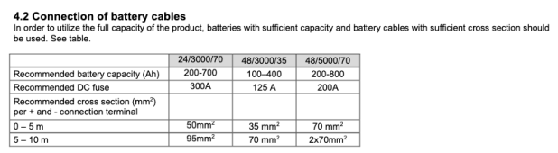
If that is what they say, then I guess you should use it...... but then the wire seems too small.I went with a 300A fuse for the battery OCPD as the Multiplus-ii manual recommended this size,
I would not make any assumptions.... particularly if you only have 2V of leeway.These are second hand panels we're using, I wonder if that would be better or worse?
Yes... I'll have to do a bit more digging. I might just go with a 2/0 AWG (70mm sq), if the only downside is that it costs a bit more?If that is what they say, then I guess you should use it...... but then the wire seems too small.
Oops, thanks for picking that up. After staring at the design for a little too long I decided to add one in, thinking I remembered the MPPT wasn't internally protected.I would not normally put a fuse next to the Solar charge controller.
The other downside is that it is a PITA to work with.if the only downside is that it costs a bit more?