diy solar

diy solar

Off-Grid Grounding: (1) Grounding System with (2) Rods OR (2) Grounding Systems?

With an entirely off grid system. The inverter "ground" refers back to the inverter case, not the earth. It is the same with the generator, the "ground" refers back to the lug on the generator frame. All your outlets and other device ground wires must return to the inverter and generator frame. If a generator is used to supply more than one fixed location it then needs a earth ground rod. Having your off grid system "grounded" to the earth will not hurt, but not help. Some Building Codes require many things that make little sense, but must be followed to please inspectors.

The solar panel frames must be connected to the earth "ground". This is to bleed static to help avoid lightning strikes. It also helps reduce damage from lightning. In Theory.
 
How do I determine if the generator is N-G bonded? What should I look for in the actual installation?
Grounding.jpg


You should separate the ground and the neutral as stated above....should be as easy as moving a wire.
 
Makes it much easier.

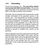
The generator is a Kohler 14RESA. The installation manual has the following language:
View attachment 98679
How do I determine if the generator is N-G bonded? What should I look for in the actual installation?
Option 1- Leave the generator N-G bond in place. Add a 3 pole transfer switch to switch from generator to inverter power. Add a ground rod at inverter and generator to limit voltage potential due to static electricity and lightning strikes nearby.

Option 2- Leave generator bond in place, install ground rod at generator for reasons above. Run generator output to inverter input. Wire like this where neutrals and grounds are common , just substitute generator for main panel. https://diysolarforum.com/attachments/1648221262034-png.88676/

If you want generator to autostart, well, it could be done, but that would depend on the generator and which option you choose. Option 2 is the cheapest and easily implemented. As the inverter and generator both bond N-G, whichever one is supplying power will have the N-G bond.

I would assume the shed is separate from the cabin. As this is a separate structure, you will need a ground rod at cabin service panel but remove the bonding screw so there isn't N-G bond in the cabin service panel.
 
If you want generator to autostart, well, it could be done, but that would depend on the generator and which option you choose. Option 2 is the cheapest and easily implemented. As the inverter and generator both bond N-G, whichever one is supplying power will have the N-G bond.
Zwy, I still have not understood how to verify/confirm whether the generator has a N-G bond. Could you please expand on how to determine this?

And yes, AGS is desired and I intend to wire the on/off generator switch to the GroWatt AIO AGS connector.

I would assume the shed is separate from the cabin. As this is a separate structure, you will need a ground rod at cabin service panel but remove the bonding screw so there isn't N-G bond in the cabin service panel.
I understand about the (2) ground rods at the cabin, but it is not clear to me whether the bonding screw is even wired in the service panel. I thought it was NOT even wired and the ground wire was connected to the neutral bar.
 
I understand about the (2) ground rods at the cabin, but it is not clear to me whether the bonding screw is even wired in the service panel. I thought it was NOT even wired and the ground wire was connected to the neutral bar.
Neutrals and grounds can all be on the same bar. Make sure that you connect to panel enclosure to this bar, also. If it's a new panel, it should come with a green screw, for that purpose.
 
Zwy, I still have not understood how to verify/confirm whether the generator has a N-G bond. Could you please expand on how to determine this?

Your post from the installation manual states it was shipped with N-G bond in place. As it was a larger generator and split phase, I was certain it was bonded.

Take a multimeter, check for continuity between neutral and ground. If there is continuity, then it is N-G bonded.

And yes, AGS is desired and I intend to wire the on/off generator switch to the GroWatt AIO AGS connector.

You have a plan, good.

I understand about the (2) ground rods at the cabin, but it is not clear to me whether the bonding screw is even wired in the service panel. I thought it was NOT even wired and the ground wire was connected to the neutral bar.
The issue will be with the ground wires on the neutral bar, it is the same as a bonding screw. If this is the panel in the cabin, you need to remove the N-G bond. Is there a equipment grounding conductor ran to the cabin? Or does it only have the neutral and 2 hots?

With the GW unit you have, this makes it much more harder to accomplish N-G bond with a bonded generator. Looking back at previous discussions we had in various threads, I recall the inverter did not bond N-G. As such, you will have to remove the N-G bond at the generator and only have N-G bond at the main service panel in the shed. The panel in the cabin would not have N-G bond but requires the ground rods/ufer ground. If the generator N-G bond can not be removed, then it would require a 3 pole transfer switch arrangement and probably 2 panels in the shed.
 
Just remove the N/G bond from the generator.
The growatt already has the N/G bond removed. (US version)
Put all neutrals and grounds on the same bar in the panel.
Make sure that the panel enclosure is also bonded to the bar.
Two ground rods 6' apart, near the panel. (Or alternative options for ground rods)
#6 thhn from ground rods to panel.
Done
 
Take a multimeter, check for continuity between neutral and ground. If there is continuity, then it is N-G bonded.
I will check for continuity between N & G at different locations and report back.

The issue will be with the ground wires on the neutral bar, it is the same as a bonding screw.
Yes, as far as I can see the ground wires currently shares the same bar with neutral at the electrical panel.

If this is the panel in the cabin, you need to remove the N-G bond.
The photo is of the EP for the cabin. And which N-G bond needs to be removed? Are we still talking about the generator N-G bond or the electrical panel N-G bond?

Is there a equipment grounding conductor ran to the cabin? Or does it only have the neutral and 2 hots?
Not sure I fully understand the question. I suspect every 120V circuit run has L1 (or L2) + neutral + ground, if this is what you asked. I need to double check but i am almost certain.

What does it mean if it has the grounding wire versus no grounding wiring for each circuit run?
 
On my generator, it is done by removing the generator core's enbell, and disconnecting the white neutral wire from the green ground wire that is bolted to the frame.

You can go online and get the instructions for your own generator, which is most likely the same.
Yes,
9 out of 10 are done this way.
But, he could have the 10th.
The manual said "junction box". (Could be the end bell, or not)
 
Take a multimeter, check for continuity between neutral and ground. If there is continuity, then it is N-G bonded.
I will check for continuity between N & G at different locations and report back.

The issue will be with the ground wires on the neutral bar, it is the same as a bonding screw.
Yes, as far as I can see the ground wires currently shares the same bar with neutral at the electrical panel.

Then the panel in the cabin is N-G bonded.

If this is the panel in the cabin, you need to remove the N-G bond.
The photo is of the EP for the cabin. And which N-G bond needs to be removed? Are we still talking about the generator N-G bond or the electrical panel N-G bond?

You have 2 separate structures with a panel in each one. With the power source in the shed, you want that panel to have N-G bond as it is the immediately after the source. If you don't have a panel in the shed, I'd install one and have it contain the N-G bond. For the cabin, add a ground busbar and move all the grounds to that busbar. Ensure there isn't any continuity from the panel case to neutral busbar.

Some will tell you that you don't need to have the N-G bond at the shed, the issue with that is bond isn't close to the source. Any ground fault between the cabin and shed could lead to equipment damage (inverter or generator) or possible shock to people and pets.


Is there a equipment grounding conductor ran to the cabin? Or does it only have the neutral and 2 hots?
Not sure I fully understand the question. I suspect every 120V circuit run has L1 (or L2) + neutral + ground, if this is what you asked. I need to double check but i am almost certain.

We need to know how many wires in the feeder circuit from the shed to the cabin.

What does it mean if it has the grounding wire versus no grounding wiring for each circuit run?

Are 4 wires run from the shed to the cabin? L1, L2, Neutral and Ground. Ground can be bare or green. Installations in the past only had 3 wires, these systems depended on the neutral for ground which was later determined to not be a good idea for ground fault protection. If you have 4 wires running between the shed and cabin, then you will be fine.
 
Went back in the thread and found your photo of the cabin panel. Do you feed power from the generator to electrical panel in the shed? If so, you need to add a ground busbar in the cabin panel, move grounds to that busbar. Remove the green screw. Install ground rods or ufer ground and run a conductor from the grounding busbar to a ground rod.

If you don't have a panel in the shed, I'd install one and do the above. The panel in the shed should have ground rods or ufer ground and contain N-G bond.
 
Do you feed power from the generator to electrical panel in the shed? If so, you need to add a ground busbar in the cabin panel, move grounds to that busbar. Remove the green screw. Install ground rods or ufer ground and run a conductor from the grounding busbar to a ground rod.
From the generator the conduit with (4) wires total (L1/ L2 / N / G) runs straight to the Cabin's electrical panel.

Please confirm if clear up to this point: add a ground busbar to existing electrical panel. Then move all grounding wires from individual circuits to the new ground busbar. Then add proper ground rod.

Assuming the above is correct, where do I connect the new ground rod to in the existing panel? I suspect in the new ground busbar, at one single point?


If you don't have a panel in the shed, I'd install one and do the above. The panel in the shed should have ground rods or ufer ground and contain N-G bond.
I do not have a panel in the shed, it goes straight from the generator thru a junction box then an underground conduit with (4) wires to the cabin.

I suspect I am almost understanding the individual options but not which solutions couple with what. For instance, I thought if I figured out how to remove the N-G bond at the generator, that I should be able to AVOID also adding an ADDITIONAL ground rod by the generator and I would keep just one single N-G bon at the existing panel, per first part of this response.

I cannot tell whether you are saying I could EITHER re-do existing panel grounding + new ground rods OR fix grounding at Generator by adding a panel and new ground rods at the generator.

Could we clarify these options?
 
If it was my system, I'd add a panel at the shed. This would allow you to utilize the bypass transfer switch of the inverter to automatically switch to generator power, you just need a trigger for the generator for automatic operation. Monitoring battery SOC would be ideal, once battery SOC drops low enough, the generator is started, then inverter switches to bypass mode.

I would N-G bond that panel with a ground rod installed, remove the N-G bond at the generator. This model inverter does not bond N-G. I would add a grounding busbar at the cabin panel, remove the green screw and move EGC's (equipment grounding conductors) to the new ground bar. Leave neutrals in place. Install a ground rod at the cabin and run EGC from grounding busbar to ground rod.

You can choose to do what you want, but adding an inverter/transfer switch into the system in a separate structure would require a bonded panel in the shed plus a ground rod at each structure if wiring according to NEC.
 
If it was my system, I'd add a panel at the shed. This would allow you to utilize the bypass transfer switch of the inverter to automatically switch to generator power, you just need a trigger for the generator for automatic operation. Monitoring battery SOC would be ideal, once battery SOC drops low enough, the generator is started, then inverter switches to bypass mode.
But why not simply rely on the Growatt AIO to monitor the battery and turn on the generator? It seems like adding an additional panel at the shed would be overkill considering the Growatt can handle these tasks, no?

Am I missing something here?

I would N-G bond that panel with a ground rod installed, remove the N-G bond at the generator.
I would add a grounding busbar at the cabin panel, remove the green screw and move EGC's (equipment grounding conductors) to the new ground bar. Leave neutrals in place. Install a ground rod at the cabin and run EGC from grounding busbar to ground rod.
Understood. Research and remove N-G bond at the generator and clean up existing panel with new grounding busbar AND adequate ground rod connected to the existing panel. Got it!

This model inverter does not bond N-G.
Is this good or bad? I am not sure what that means to me.

but adding an inverter/transfer switch into the system in a separate structure would require a bonded panel in the shed plus a ground rod at each structure if wiring according to NEC.
Can I NOT add a transfer switch in the shed and simply remove N-G bond at generator and fix the grounding at the cabin's panel?

Would that suffice?
 
If it was my system, I'd add a panel at the shed. This would allow you to utilize the bypass transfer switch of the inverter to automatically switch to generator power, you just need a trigger for the generator for automatic operation. Monitoring battery SOC would be ideal, once battery SOC drops low enough, the generator is started, then inverter switches to bypass mode.
But why not simply rely on the Growatt AIO to monitor the battery and turn on the generator? It seems like adding an additional panel at the shed would be overkill considering the Growatt can handle these tasks, no?

Am I missing something here?


As I stated before, how to automatically turn on the generator will be up to you to figure out. I'm not aware of any function in a GW inverter that will do this.

I would N-G bond that panel with a ground rod installed, remove the N-G bond at the generator.
I would add a grounding busbar at the cabin panel, remove the green screw and move EGC's (equipment grounding conductors) to the new ground bar. Leave neutrals in place. Install a ground rod at the cabin and run EGC from grounding busbar to ground rod.
Understood. Research and remove N-G bond at the generator and clean up existing panel with new grounding busbar AND adequate ground rod connected to the existing panel. Got it!

Remove N-G bond at the cabin service panel.

This model inverter does not bond N-G.
Is this good or bad? I am not sure what that means to me.

For your situation and how this would be wired, that is good. It's no different than a generator having or not having N-G bond.

but adding an inverter/transfer switch into the system in a separate structure would require a bonded panel in the shed plus a ground rod at each structure if wiring according to NEC.
Can I NOT add a transfer switch in the shed and simply remove N-G bond at generator and fix the grounding at the cabin's panel?

Would that suffice?


You don't need a separate transfer switch, there already is a transfer switch built into the GW that allows bypass operation. Use it instead. You need a properly sized breaker ahead of the GW unit. That is why you need a breaker panel in the shed plus it allows N-G bond to be there which is close to source. Added bonus is you can add a circuit or two in the shed. A main service panel rated for 100A cost about 100 bucks anymore and usually includes a main breaker.

Have you ever watched Mike Holt's videos on grounding?
 
At my own place, I was able to fully pound my rods the whole 8', so I don't have any personal experience with alternatives. There might be two, but don't treat me as the expert. I believe the first is a ground plate, perhaps 24" X 24" square, buried ~18" in the ground, or secondly, a bare copper wire, extending X number of feet, also buried ~18" deep.

I didn't research these alternatives thoroughly because I didn't have to, but I've seen them mentioned before by others here in previous grounding threads.

What might help you is to first take a grinder and put a sharp point on one end of the rod, and then support the rod with steel pipe as it is being pounded in. I saved 6', 4', and 2' lengths of scrap steel pipe just for situations like this. Slipping the pipe over the rod keeps the rod from bending, and helps direct all the force directly downwards. I used a post-puncher for driving the rods, which definately helped.

What might work, but this could be a code violation, is to cut each rod in half and pound the four half-length rods into the ground, 6 feet apart. Don't know if an inspector would flatly say NO to this. Again, all four mini-rods would be wired in series, with one unbroken/spliced ground wire. This is just my "try to make it work" idea. Don't know if it is reasonable?
"What might work, but this could be a code violation, is to cut each rod in half and pound the four half-length rods into the ground, 6 feet apart. Don't know if an inspector would flatly say NO to this. Again, all four mini-rods would be wired in series, with one unbroken/spliced ground wire. This is just my "try to make it work" idea. Don't know if it is reasonable?"

I did it this way for a project I had done years ago. I sold the house a few months ago and the buyers inspector saw it and said that was fine to do. But that was here in Arizona. Good Luck!
 
Back
Top