diy solar

diy solar

Off-Grid Grounding: (1) Grounding System with (2) Rods OR (2) Grounding Systems?

As I stated before, how to automatically turn on the generator will be up to you to figure out. I'm not aware of any function in a GW inverter that will do this.
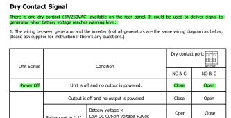
I believe the GW unit offers that, see below:

1655741466671.png

You need a properly sized breaker ahead of the GW unit. That is why you need a breaker panel in the shed plus it allows N-G bond to be there which is close to source.
Just to be on the same page, if I do remove N-G bond from existing cabin electrical panel and I add a new panel inside the shed, I would need only grounding rods by the shed. Is this correct?
 
I further inspected the existing installation and this is what I have found so far:

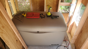
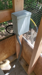
This is my Generator Setup in the shed, with a junction box next to it:

1655741849269.png

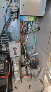
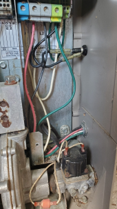
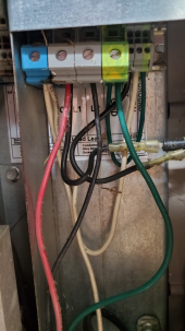
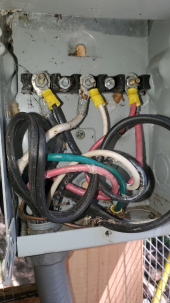
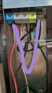
Inside the Generator I have (4) wires: Red / White / Black / Green. The green wire I believe is the GROUND wire. I am still trying to figure out how to "remove the N-G bond inside the generator".

1655741968727.png
1655741992372.png
1655742012432.png

The (4) wires leave the generator and go to a junction box inside the shed. In this junction box, the green wire "turns" into a bare copper wire:

1655742133906.png
1655742177576.png

The (4) wires run to the Cabin and land in the existing 100A panel, as shown in an older picture of the EP.
 
Pull out that white wire going from the small terminals to the big terminals in the generator connection box.
 
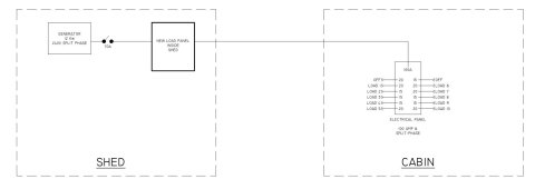
I am trying to pick the correct sub-panel to be installed in the shed but I could use some help.

I just realized the Generator has a 70A circuit breaker while the main electrical panel inside the cabin has a 100A main breaker.


MF_Off Grid Electrical Design-Model.jpg

How to pick the breaker for the circuit from the shed new panel to the cabin existing EP? I suspect it has to be equal (70A - Any loads in the external shed panel).
 
I am trying to pick the correct sub-panel to be installed in the shed but I could use some help.

I just realized the Generator has a 70A circuit breaker while the main electrical panel inside the cabin has a 100A main breaker.
The output breaker on the load panel in the shed should be sized according to the generator output. Doesn't really matter what size is on the panel in the cabin. 70A or slightly above would work.

If you are adding an inverter to this mix, the breaker should be sized according to peak output of the inverter or generator, whichever is smaller.
 
If you are adding an inverter to this mix, the breaker should be sized according to peak output of the inverter or generator, whichever is smaller.
Yes, I am adding the Growatt 8kW inverter in the mix.

I cannot tell from the spec sheets for the inverter what is the peak current:

Inverter PDF

Should I calculate it or must it be listed under a different inverter document?
 
Yes, I am adding the Growatt 8kW inverter in the mix.

Just remember this inverter has higher idle consumption and inverter efficiency is around 88%. What are you planning to run with it?
I cannot tell from the spec sheets for the inverter what is the peak current:

Inverter PDF
Should I calculate it or must it be listed under a different inverter document?
The company you're buying it from should have the manual available for download on their site.
 
The output breaker on the load panel in the shed should be sized according to the generator output. Doesn't really matter what size is on the panel in the cabin. 70A or slightly above would work.

If you are adding an inverter to this mix, the breaker should be sized according to peak output of the inverter or generator, whichever is smaller.
Breakers are sized to the wire size and function to protect it the wire from burning down your house.
Wire is sized to the amount of current going through it and what it is running.
Components are supposed to be designed to protect themselves or state the breaker size and wire needed.
 
Breakers are sized to the wire size and function to protect it the wire from burning down your house.
Wire is sized to the amount of current going through it and what it is running.
Components are supposed to be designed to protect themselves or state the breaker size and wire needed.
Yes, exactly. Breaker size at the source is paramount. The inverter or generator output is what will determine both the size of the breaker and the wire size needed, whichever is the lesser rating of the two.
 
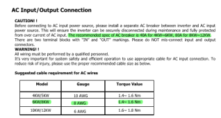
Okay, the manual has the following requirements:

1656513275625.png


So the inverter requires 80A breaker while the Generator requires 60A.

So I believe I need to have a 60A breaker on the new circuit from the shed to the cabin.

Kosher?
 
Okay, the manual has the following requirements:

View attachment 100579


So the inverter requires 80A breaker while the Generator requires 60A.

So I believe I need to have a 60A breaker on the new circuit from the shed to the cabin.

Kosher?
That would be correct, that would be close to inverter rated output of 8Kw. This protects both the generator and inverter due to overload.

If you end up with nuisance tripping under inverter power due to the 60A breaker, one could use an interlock. Square D used to make these for panels that didn't have a large main breaker at the top of the panel at the lugs, more of a backfed panel setup. http://tumblebones.com/product/sd100xul-square-d-qo-generator-interlock-kit-100-amp-main-breaker/ which would allow you to have a 60A breaker for the generator and 80A breaker for the inverter. This interlock only allows one breaker to be switched on. The later interlocks are much different and might be adaptable to your panel also.

I'd run the 60A if you want the generator to kick on automatically.
 
Grounding info, the best I have found. Simpler, but not simple.
There are four parts, this is one, for residential grounding.
Try and go thru it all. Digest it, refer back to each section as needed:
 
Back
Top