Just Linux - some python scripts to pull in the data and push it to Grafana. Should be easy enough to run on Windows and Mac as well though.


You are using an out of date browser. It may not display this or other websites correctly.
You should upgrade or use an alternative browser.
You should upgrade or use an alternative browser.
Off-grid Solar / Battery monitoring and control freeware
- Thread starter BarkingSpider
- Start date
I am wanting so bad to do this for my MPP LV6548's and heltec BMS!Yep, as soon as I have the BMS side of things done.
Please tell me RJ12 Cables PIN asignment. I tried connection but it did not work.If you want a cheap monitoring solution, I can now get great stats from the Renogy Wanderer 10a Li using a Python script.
The little Renogy is under $20.
You will need a $25 Pi Zero and make a special USB-RJ6 cable. Everything else is freeware.
# renogy.py
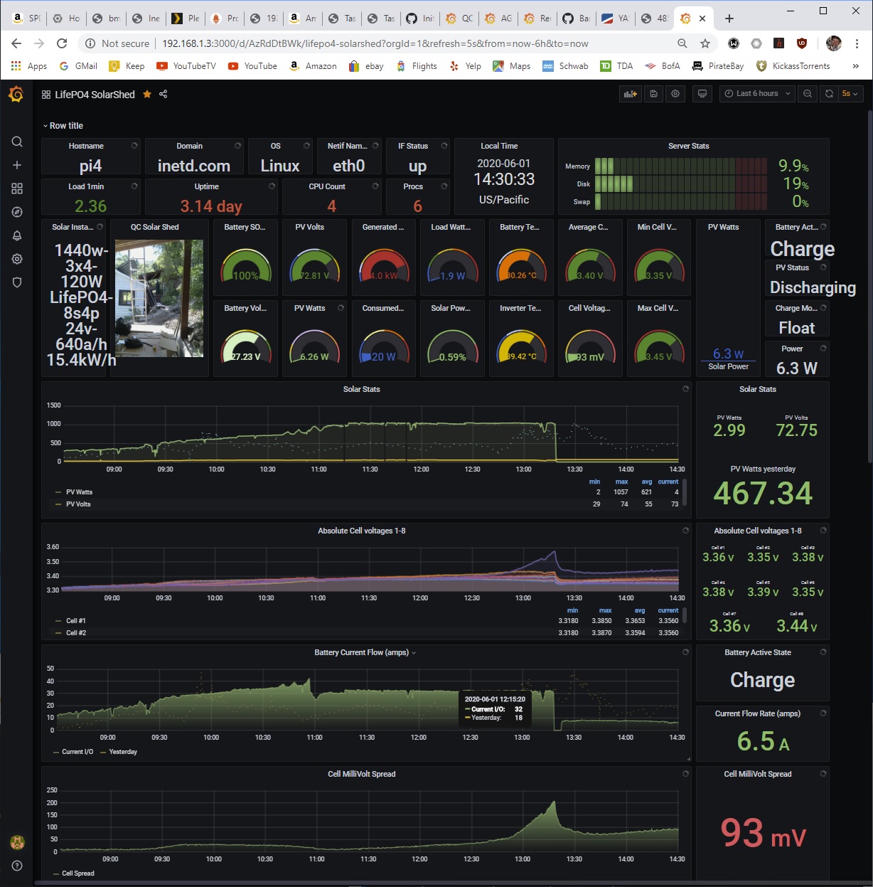
Reading Renogy Wanderer data...
Battery SOC: 100.0 %
Battery Voltage: 26.6 v
Charging Amps: 0.08 a
controller temp: 9.472 C
Load watts: 4 w
PV volts: 27.4 v
PV amps: 0.03 a
PV watts: 2 w
bat min volts: 26.6 v
todays charge power: 80.0 w
todays discharge power: 42.0 w
View attachment 14277
View attachment 14281
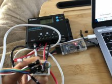
Im connected to a small 24v A123 LifePO4 bank I use for testing, and also monitoring cell voltages with a 8s Chargery BMS. The PiZero plugs into the USB ports of the Renogy for power only. All the data comes from the RS232 port.
What's exciting is you can parallel these 10a Renogy units to make a cheap 40amp charger and get the full features of a unit that costs $200.
I'll clean up the code and post the howto ASAP. Joe.
WANDERER =================== DSD TECH SH-U09C (5V Setting) ==== MBP USB PORT
1: TXD(5V) ===================== RXD
2: RXD ===================== TXD
3: GND ===================== GND
4: GND
5: PWR(10V<)
6: PWR(10V<)
Attachments
Last edited:
I got a error message when controller unpluged from battery.
Reading Renogy Wanderer data...
MinimalModbus debug mode. Writing to instrument (expecting 7 bytes back): '\x01\x03\x00\n\x00\x01¤\x08' (01 03 00 0A 00 01 A4 08)
MinimalModbus debug mode. No sleep required before write. Time since previous read: 1012.0 ms, minimum silent period: 4.01 ms.
MinimalModbus debug mode. Response from instrument: '' () (0 bytes), roundtrip time: 2005.6 ms. Timeout setting: 2000.0 ms.
Failed to read from instrument
Opened new tmp file /tmp/Renogy.prom.tmp
Reading Renogy Wanderer data...
MinimalModbus debug mode. Writing to instrument (expecting 7 bytes back): '\x01\x03\x00\n\x00\x01¤\x08' (01 03 00 0A 00 01 A4 08)
MinimalModbus debug mode. No sleep required before write. Time since previous read: 1027.4 ms, minimum silent period: 4.01 ms.
MinimalModbus debug mode. Response from instrument: '\x00\x00\x08\x10A\x18\x83' (00 00 08 10 41 18 83) (7 bytes), roundtrip time: 0.1 ms. Timeout setting: 2000.0 ms.
Traceback (most recent call last):
File "./RenogyWanderer.py", line 272, in <module>
readRenogy(file_object)
File "./RenogyWanderer.py", line 64, in readRenogy
register = renogy.read_register(0x00A)
File "/usr/local/lib/python3.7/site-packages/minimalmodbus.py", line 258, in read_register
return self._genericCommand(functioncode, registeraddress, numberOfDecimals=numberOfDecimals, signed=signed)
File "/usr/local/lib/python3.7/site-packages/minimalmodbus.py", line 697, in _genericCommand
payloadFromSlave = self._performCommand(functioncode, payloadToSlave)
File "/usr/local/lib/python3.7/site-packages/minimalmodbus.py", line 798, in _performCommand
payloadFromSlave = _extractPayload(response, self.address, self.mode, functioncode)
File "/usr/local/lib/python3.7/site-packages/minimalmodbus.py", line 1075, in _extractPayload
raise ValueError(text)
ValueError: Checksum error in rtu mode: '\x18\x83' instead of 'h2' . The response is: '\x00\x00\x08\x10A\x18\x83' (plain response: '\x00\x00\x08\x10A\x18\x83')
BarkingSpider
Carbon Lifeform
These images should help with your pinout problems. Check each connection with a mutimeter!

@BarkingSpider Thank you for your help.
My work doesn't seem to be wrong.
But there is no response from WANDERER. I tried three types of USB and serial conversion adapters.
I also tried Windows and Mac, some Python programs and serial test tools, and MODBUS test tools, but there was no response.
I suspected there was a problem with the WANDERER interface, but the BT-1 module worked fine.
I would like to try a sniffer for communication between the BT-1 module and WANDERER.
If you have any hints or advice, please let me know.
Thank you for your kindness.
These images should help with your pinout problems. Check each connection with a mutimeter!
BarkingSpider
Carbon Lifeform
I'll do some more checking later today, but first ensure
1) your adaptor is true RS232
2) the RJ connector is really making contact with the pins in the renogy SCC, I had trouble with this.
3)You need to test the data connection with my python PI code (on GitHub, link below) as it's modbus protocol, not a serial data stream. Modbus responds to queries. The line will be quiet without the correct query.
Maybe you can find a modbus query tool for windows?
Hope this helps. Joe.
Maybe you can find a modbus query tool for windows?
That's what he is using according to the screenshot.
I have tried the following 3 adapters.1) your adaptor is true RS232
A) Plugable USB to Serial Adapter Prolific PL2303HX Rev. D Chipset
B) PL2303HX-RS232-Serial-TTL-Adapter
Amazon.com: PL2303HX RS232 USB to TTL Cable, USB to TTL Serial Adapter STC Download Cable : Electronics
Buy PL2303HX RS232 USB to TTL Cable, USB to TTL Serial Adapter STC Download Cable: USB Cables - Amazon.com ✓ FREE DELIVERY possible on eligible purchases
www.amazon.com
I checked the contacts with a multimeter. Each voltage was below when the 12V battery was connected.2) the RJ connector is really making contact with the pins in the renogy SCC, I had trouble with this.
1.TXD -> 3.GND -5.645V
2.RXD -> 3.GND -0.1V(104.5mV)
3.GND -> 4.GND 0V
4.GND -> 3.GND 0V
5.PWR -> 3.GND 10.8V
6.PWR -> 3.GND 10.8V
I tested with some python codes on MacOS X and Windows modbus test tool.3)You need to test the data connection with my python PI code (on GitHub, link below) as it's modbus protocol, not a serial data stream. Modbus responds to queries. The line will be quiet without the correct query. Maybe you can find a modbus query tool for windows?
For read request flags, I referred to the RENOGY MODBUS protocol documentation.
01 : Dev Address
03 : Fuction Code
00 0A 00 01 : Query Data
A4 08 : Check Sum
*Send with RTU mode
I'm stuck, so I'm thinking of trying to see the difference between BT-1 and USB-Serial module.
Also, I have multiple raspberry pies, so I would like to try them as well.
Thank you for your kindness.


BarkingSpider
Carbon Lifeform
Congratulations! What did you change to get it working?
Thank you @BarkingSpider !
I edited this line.
 github.com
and
I edited a minimalmodbus module too.
I edited this line.
SolarShed/RenogyWanderer.py at 729f4927d5179f8661b2162963773c452d102f82 · BarkinSpider/SolarShed
Realtime data monitoring of solar power equipment metrics - BarkinSpider/SolarShed
github.com
27c27
> renogy = minimalmodbus.Instrument(devName, 1)
---
< renogy = minimalmodbus.Instrument(devName, 255)
and
I edited a minimalmodbus module too.
> diff /usr/local/lib/python3.7/site-packages/minimalmodbus.py /usr/local/lib/python3.7/site-packages/minimalmodbus.py~
2078c2078
< SLAVEADDRESS_MAX = 255
---
> SLAVEADDRESS_MAX = 247
===> Work fine.A) Plugable USB to Serial Adapter Prolific PL2303HX Rev. D Chipset
https://www.amazon.com/dp/B00425S1H8/
===> Not work.B) PL2303HX-RS232-Serial-TTL-Adapter
https://www.amazon.com/dp/B08JTVNGL9/
===> Not work.C) DSD-TECH-Adapter-FT232RL
https://www.amazon.com/dp/B07BBPX8B8/
JAJ_DDC_Controls
New Member
- Joined
- Mar 28, 2021
- Messages
- 1
I'm having issues with the install instructions. https://github.com/BarkinSpider/SolarShed/blob/master/Pi Setup Cheat Sheet
Is there a Raspberry Pi image with the software all ready loaded that might be a faster way for a noob like me to get it operational?
It would be faster for me to read the instructions and look at operational code to understand the instructions.
My experience is in building automation, so I am interested in this project to teach myself a new skill set.
Testing Configuration:
Renogy Wanderer 10 Amp 12V/24V PWM Negative Ground Solar Charge Controller
USB to serial adapter, custom cable made and tested for correct voltage from the RS-232 port.
AGM B.B Battery (12v 8Ah) BP8-12 Qty 2 in parallel (Fused at 7 1/2 Amps)
Solar Panel is an adjustable power supply 0 - 24 VDC at 20 Amps set at 15.4 VDC (Fused at 7 1/2 Amps)
Raspberry Pi Model B Plus Rev 1.2 Software loaded Raspberry Pi Imager v1.6 with "Raspberry Pi 0S (32bit)" Power from the USB from the Wanderer (Fused at 2 Amps)
I am happy to buy a new PI if that will make me compatible with the project image file.
Last edited:
I'm here to share my success with my solar Garden Pi setup")
Setup:
2 x 100W Newpowa Polycrystalline Panels
Renogy Wanderer 30A
Optima BlueTop AGM Battery
Raspberry Pi 3B+ running:
- BarkingSpider's SolarShed scripts (connected by RS232 to Wanderer)
- Motioneye camera streaming (connected to Day/Night Pi Camera module)
- OpenSprinkler irrigation controller (using the OpenSprinkler Pi board extension)
- node exporter is shipping to both a on board Prometheus db and a central one on my network
- Since it is also powered by solar and on the edge of wifi, I need to be able to see when it goes down and try to figure out why, so having both records makes it handy
wired the pi to Wanderer like:
RJ12 running through CAT-6 to: Sysly DB9 RS232 Serial to Terminal
then: USB to RS232 Adapter with PL2303 Chipset into the USB port of Pi
I am setting up a garden a bit away from my main house, and I didn't want to run electric out there to power a irrigation system. So I started down this path with a couple of panels, a Wanderer (cause they are cheap), and a battery. The idea is the solar setup would power: a Pi for irrigation timer, a garden webcam to monitor for critters/document the garden, the irrigation solenoids to open up, and a 12V on demand water pump that will turn on only when the sprinkler valves are open. I started getting things together and experimenting, but got frustrated with trying to diagnose everything blind. Then I came across this repo and man, I'm in data heaven ?.
Thanks so much for putting this out there for all !! I only had to modify the dashboard for my preferences, but I'm extremely happy with this high tech, but reasonably priced set up. I still have to finish the rest of the setup and I will be reporting back on my progress. The camera is sitting inside the box with the battery and Wanderer, right now, but eventually I'll get it pointing out on the garden for a much better view.
Thanks again!!
BarkingSpider
Carbon Lifeform
Great job, that made my day. happy easter!
BarkingSpider
Carbon Lifeform
Great yourself a new pi 4 or pi zero. Take the time to understand the steps. The experience is worth every minute of your time. You will be using those skills for years to come. Above all have fun! Joe.I'm having issues with the install instructions. https://github.com/BarkinSpider/SolarShed/blob/master/Pi Setup Cheat Sheet
Is there a Raspberry Pi image with the software all ready loaded that might be a faster way for a noob like me to get it operational?
It would be faster for me to read the instructions and look at operational code to understand the instructions.
My experience is in building automation, so I am interested in this project to teach myself a new skill set.
Testing Configuration:
Renogy Wanderer 10 Amp 12V/24V PWM Negative Ground Solar Charge Controller
USB to serial adapter, custom cable made and tested for correct voltage from the RS-232 port.
AGM B.B Battery (12v 8Ah) BP8-12 Qty 2 in parallel (Fused at 7 1/2 Amps)
Solar Panel is an adjustable power supply 0 - 24 VDC at 20 Amps set at 15.4 VDC (Fused at 7 1/2 Amps)
Raspberry Pi Model B Plus Rev 1.2 Software loaded Raspberry Pi Imager v1.6 with "Raspberry Pi 0S (32bit)" Power from the USB from the Wanderer (Fused at 2 Amps)
I am happy to buy a new PI if that will make me compatible with the project image file.
Hey Joe,
Can you help me out with this code snippet? I have a temp sensor attached to my wanderer that monitors battery temp. I see there is a code snippet that is in RenogyWandrer.py for these, but it seems like it is the same 0x103 register as the scc temp. I'm not very solid at all on python, so what is the best way to switch the output to the battery temp?

Can you help me out with this code snippet? I have a temp sensor attached to my wanderer that monitors battery temp. I see there is a code snippet that is in RenogyWandrer.py for these, but it seems like it is the same 0x103 register as the scc temp. I'm not very solid at all on python, so what is the best way to switch the output to the battery temp?
Similar threads
- Replies
- 9
- Views
- 451
- Replies
- 9
- Views
- 461
- Replies
- 1
- Views
- 392
- Replies
- 3
- Views
- 152