diy solar

diy solar

Off grid solar project

Looking good!
Thanks.

A downside of having improved the angle, is that unless I totally drain the battery at night, on a sunny day it is fully charged by 2pm. What do you do in this situation? I unplugged the solar panels, and I have ordered an isolator switch.
 
unless I totally drain the battery at night, on a sunny day it is fully charged by 2pm. What do you do in this situation?
The charge controller should look after that. Once the batteries are full it will stop sending charge to the batteries (and stop drawing power from the PV array).
 
Yes, I've widened the margins between battery over voltage and release value, because it kept turning on an off, which I didn't think was good for the battery. Now batt over voltage is 27.2V and release value is 26.8V.
 
Yes, I've widened the margins between battery over voltage and release value, because it kept turning on an off, which I didn't think was good for the battery. Now batt over voltage is 27.2V and release value is 26.8V.
Is that in your charge controller or BMS?
 
Is that in your charge controller or BMS?
The BMS; and I've just increased battery over voltage to 27.4, with the release value kept at 26.8. Cell over voltage is 3.45V with a release value of 3.40.

I'll still feel more comfortable with a physical isolator switch, as the days get longer.

I have ordered a second set of 8 cells from Shenzhen Luyuan, and when I build the second battery it won't be an issue any more - unless I get more panels!
 
I've always called it anglign, I guess you could call it an aluminium angle extrusion.

Just reading this thread for the first time and was intrigued to read the above.

I think it's meant to be "angle iron" ... though in this case you are after 'aluminium angle'

It's funny how we can get caught out with words or names we've heard for years ... but never quite worked out how they are spelt. Happens to me too often myself. :)
 
It's funny how we can get caught out with words or names we've heard for years ... but never quite worked out how they are spelt. Happens to me too often myself.
The converse is someone who mispronounces a word. Usually it means they learnt it from reading and can spell it.
 
The converse is someone who mispronounces a word. Usually it means they learnt it from reading and can spell it.
Haha, yep. The older I get, the more I second guess myself on spelling and also pronunciation. Used to be really confident, having read prolifically as a young person ... but not so much any more. (just had to spell check prolifically!!!)
 
At last the panels are on the shed roof.

PanelsonShed.jpg

And looking neater after a bit of cable management.

PanelsAfterCM.jpg
 
Panels look great, and secured. You need to set the BMS to protect the cells from abuse. Settings should be at the outer limits the industry fees acceptable, or slightly more conservative. Then set your charge controller to work within those parameters. If the charge controller doesn’t stay within those, then the BMS is a backup. I have operated LFP for 3 years and so far have never had a BMS open.
 
I have received another 8 cells from Amy Wan of Shenzhen Luyuan. Once again they were so well packed and in such pristine condition I was loathe to unpack them. But I pulled myself together and have now constructed a second 8s 24v battery and put it in parallel with the first.

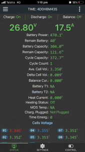
This time I used a JK Smart (JK-B2A8S20P) BMS, mainly because I wanted to try out one with active balancing. It was also half the price of the Overkill BMS I am using with the first battery. And this is reflected to some extent in the workmanship. The cables are much shorter, one of the measurement cables fell out of the plug and had to be pushed back in; and I had to solder the main cables on to the board myself (something I don't enjoy).

The Bluetooth has a shorter range, but it works and I had no difficulty downloading the app and getting it talking to the BMS.

JKSS1.PNGJKSS2.PNG

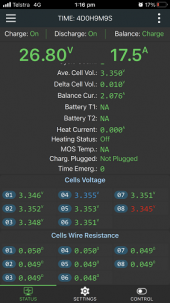
There are no graphics in the app, but the information is all there, albeit spread over more space then my phone can display. Taking up some space is a display of the cell and measurement cable resistance. I’m not quite sure why I need that, except perhaps to confirm that the contacts in my terminators and the main plug are good. But anyway it seems to work just fine.

The cells were shipped very well in balance, and there are now 16 of them sharing my 800W base load and my 8 old and underperforming 190W panels, so I haven’t seen very much active balancing going on just yet (although I've just noticed in the second screenshot there is a small balancing current showing).

In fact there seems to be more balancing happening between the two batteries, than between the cells within each battery.

1664188907566.png

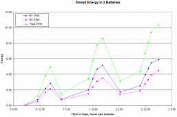
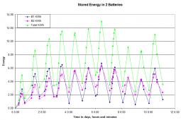
The chart above shows my first battery is charging and discharging faster than the second. Two questions sprang to mind. Why is this and does it matter? In answer to the first I measured the total resistance between the negative terminal and inverter for both batteries. And low and behold, for the first it was about 3.2 mΩ and for second about 4.5 mΩ. My explanation is that the BMS cables were too short to reach the inverter, so I had to add in another cable and another connection.

Does it matter? Using the formula P = I2R, at a base load current less than 20A that’s 1.3W being lost in the first circuit and 1.8W in the second – way less than the 25W being consumed by the inverter on idle. I worried for a moment that the first battery would “wear out” faster than the second, but the very presence of the second battery means that the first is “wearing out” slower than it was before, so I am not losing any sleep over it.
 
Last edited:
If it were me, I would get the resistance balanced. No point in having 2 and only using 1.
Fair point, I should probably put that on my list of things to do.

I also need a few more panels, because the ones I have are not filling the combined battery to capacity.
 
Talking of things not being quite in balance, I have been disappointed by the power output of my panels with the sun at full strength, so now that they have been fixed to the roof I did some belated diagnostics.

For each pair of panels I measured the current flowing through the positive lead. For completeness I also measured the combined current flowing through the positive lead into the charge controller. The currents were 4.6, 3.9 4.5 and 4.0A from the panel pairs (adding up to 17A) while the combined current was 17.5A (probably a measurement error in there somewhere).

So two pairs are under performing, and I’d wager there is only one bad panel in each pair. So if I’d tested the panels in advance I could perhaps have squeezed an extra half amp out of the set and gained another 30W.

The OFG has a link to a solar panel tester, but I baulked at paying around $100 for something I would only use once. And for that price I could buy a couple of extra second hand panels and gain another 4-5A or in the order of 300W. But, with the benefit of hindsight, if one can force the probes of an ordinary multimeter into the solar panel connectors, there is probably something to be said for making at least some measurements before organising an array of second hand panels.
 

If your panels are wired in some series/parallel configuration, then choosing similar currents to wire in series could produce a bit more.
If you find any with bad diodes you can replace those.
 
Last edited:

If your panels are wired in some series/parallel configuration, then choosing similar currents to wire in series cold produce a bit more.
If you find any with bad diodes you can replace those.
Yes, thanks, that's what I'd do if I did it all again. I am using the 2S4P configuration.
 
JKSS3.PNG
I can’t help posting this screenshot. It shows a zero voltage difference between cells. I don’t think I’ve ever seen that before. Either the active balancing is doing its job, or it is a very well balanced set of cells – probably both.

I should add that I have done none of the manual top balancing or bottom balancing that some people so painstakingly do. I just unpacked the cells, joined them together in a series string, wired in the BMS, connected the inverter and charge controller, and the battery was live.

I have read some pundits suggesting that you don’t need Grade A cells to power a house, but I disagree. The house doesn’t drain as much current as an EV, but having well matched top quality cells not only not only improves ease of management, but also gives you a greater practical depth of discharge.

I have posted a screenshot earlier in this thread of what I believe to be sub-EV quality cells showing a voltage different approaching 400 mV. I have set my BMS to give me a roughly 80% DoD to extend the battery life. The voltage ranges from roughly 3 to 4.2 V – a difference of 1.2 V. Imagine I had a difference of 400 mV between my highest and lowest potential cells. That would cut the usable capacity of my battery by something approaching a third.
 
Please don’t charge LFP cells over 3.65 volts per cell ever. Don’t charge to 3.65 on a regular basis. A paper by a university I Read said if LFP cells reach 4.2 volts or 2 volts to take them out of service, they can’t be trusted and will fail at some point.
I set the BMS to 3.65 and 2.5 volts per cell but set the charging more conservative than that.8703FF9B-CC45-4523-9DA0-D13906861EC0.png
 
I set the BMS to 3.65 and 2.5 volts per cell but set the charging more conservative than that.
I quite agree, and I set my BMS to 3.45 and 3.00.

1664950185067.png
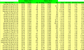
The nominal capacity of my two batteries is 16 KWh and 80% of that is 12.8 KWh. You can see from the chart above that I mostly stay well within that range. Here is a snapshot of some of the data behind that chart.

1664950455601.png

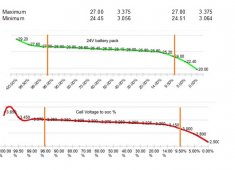
Over the whole period of operation so far, my maxima and minima are as follows:

Voltagerange.jpg
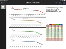
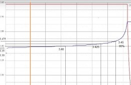
I have marked them on your charts, although I note your charts are discharge charts, and I think to gauge the capacity associated with voltage maxima, you need to use a charging chart.

OFGBChargeDIYS.jpg

I've marked mine on a chart borrowed from the OFG running tests on cells with the same specs as mine. I'm not sure exactly what percentage capacity 3.75V represents, but by eye I'd estimate something in the order of 90%. So the capacity range associated with my voltage range is not far off 10% to 90%, which is what the manufacturer recommends for maximum cell life expectancy.
 
Back
Top