diy solar

diy solar

Off grid solar system for maintaining half a dozen batteries (ATV's, tractors, boats, etc).

Before you do spend a lot of money on stuff, why not spend a little on a Kill-O-Watt meter and see how much power your battery tenders take now? Here is one.


I got one for just $26 at Harbor Freight.

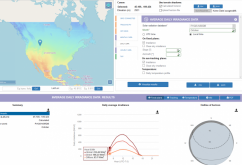
So take one of your battery tenders, plug it into this, and let it run for 2 or 3 days, and see how many watt hours it needed. Divide that by the hours, and then multiply by 24 to get the watt hours per day. Do that for each of your batteries. If you find a battery that needs a lot more than the others, it either has a drain on it, or the battery is failing already. Add up the watt hours per day needed for all of them, and then double it. That is the minimum amount of solar you will need. We already figured you may only get 1.9 "sun hours" a day in the dead of winter, with your panel angled correctly. So for example, if your figure works out to needing 500 watt hours per day, you can divide by 1.9 and get 500/1.9 = 263.16 watts of solar panel. So go with a 300 watt panel. Plan for double to allow for bad "sun days" and round up to more.

My pig of a refrigerator pulls a near constant 180 watts. The Kill-O-Watt came up to nearly 4,300 watt hours a day. I get almost 4 sun hour here in winter in So Cal. So just my refrigerator needs a bare minimum of 1,075 watts of solar panel to run "off grid" all winter. And double that to 2,000 watts to cover a bad day. Yeah, it's not maintaining little batteries, just an example of how the math works. I have 4,800 watts of panels, but a lot more load than just the fridge as well. I am not off grid, but it still helps to do the math to see what it would take. In hind site, I should have put up a few more panels.
 
I did say to do the test for a few days on each of the batteries. That is even in the part you quoted.

A good battery on a device with no static drain might need very little power. A battery in worse shape on a device with some static drain in the electronics could need quite a bit more energy. All of the energy needed to keep all 6 batteries alive will need to come from the solar panel(s) in just 1.9 sun hours a day. And at the end I said DOUBLE it. My home system averages about 20 KWH per day, but I still get cloudy day where it has fallen to only 2.2 KWH's. Hopefully that does not happen often. Plan around a good average with a little extra pad built in. If you get a few bad days, the batteries should be fine.
 
This would assume all batteries were the same size, type, age and at the same state of charge as the charger was set for.
Don't overcomplicate: you put all batteries at 13,8V float to pass the winter and that is it...
In fall when you decommission the batteries from the gadgets, you let them idle for 2 weeks, if one of them got low, then it is time to replace it.
 
I agree, start the draw test with the batteries already at full charge. We just want to find the power needed to keep them floating.

Depending on the vehicle or device, maybe they want to keep the parasitic load powered. If so, we should include that drain in the calculation. Needing an amp while the sun is up is not too bad, just make sure the whole day of sun is enough to account for it. IF there is nothing critical, then disconnected is better.

The 1.9 sun hours is from the irradiance calculation of his location in winter up in Canada. Due to the bad angle of the earth, even with the panel tilted up, the max power will not even be close to the panel rating. The watt hours of sun hitting the panel is about 1.92 KWH/day/square meter. So the total energy from any panel will be it's rating in hats x 1.92 to get the watt hours in a day under those conditions. In Colorado, it might be 3.5 sun hours, and here in So Cal, even in the dead of winter, it is about 3.5 sun hours for my panel angle. The whole day puts as much as perfect sun for just this much time, but in reality, it is less energy over a longer time, with a slope up to solar noon, and a slope back down again.

We are offering a few options based on different budgets. The original poster can weigh the pros and cons

All similar chemistry batteries in parallel on a charge controller is the absolute cheapest option with a few possible ways it could fail. If the bateries are in fair shape, and you have enough solar to handle any parasitic loads, this should work fairly well. A battery failure, or a loss of solar power would be bad for all of the batteries though.

Next up is using separate charge controllers off of the solar panel. MPPT units will be confused as the different units try to search. This is one odd case where PWM controllers might actually work better, assuming they actually do have an inductor in them. The real cheap ones that just directly switch the panel to the batteries would sort of work, but certainly not the best. The adjustable buck converter I got for testing batteries would probably work just fine with the solar panel just charging a large capacitor. At a low load, the cap could charge up to the VOC of the solar panel. There are adjustable PWM buck converters, and even fixed 13.8 volt ones that would do the job as well as a dedicated float charger.

The "best" setup is to use a larger solar array and charge controller to charge a battery bank. Then have that battery run separate DC-DC battery maintainers for each battery being charged. Or use an inverter to power normal AC line battery maintainers. This is a bit more expensive as you have a bit more losses and equipment to deal with. But on the flip side, each battery is being handled properly with no worry of the others causing a problem. If one battery does fail, it can't hurt the others. Using a good sized battery and inverter also gives you a mains power source to run lights or power tools as well.
 
Over complicate??
It's clearly obvious that this would all be significant factors for anyone that knows anything about batteries.
...
I am surprised that so many are advising corner cutting with poor battery management practices here especially when the cost of doing it properly is so low.
We are not speaking of batteries on operative use, dude! Just to keep them at float during the winter.
Of course the figure would be entirely different, f you were using them in an off-grid operational environment, which is incidentally my speciality. :p

Putting separate SCCs is vain: in the weak morning sun, after a night of running idle, all SCCs will fully conduct anyway and the scarce morning current from the panel will flow to 100% to the strongest battery anyhow.
When a lead acid approaches its floating level again, its internal resistance grows rapidly so that, at the float charge, the system will find an equilibrium.

I agree, start the draw test with the batteries already at full charge. We just want to find the power needed to keep them floating.
For a usual cranking battery in good shape, expect just a few mA at 13,8V float, once fully charged.
You will of course need more -much more- after the (long) night at idle and the panel will not be able to deliver the morning current, but that is OK.
The important thing, is that they finally get at 13,8V at least a couple of times each week.
 
-- and you have enough solar to handle any parasitic loads, this should work fairly well. A battery failure, or a loss of solar power would be bad for all of the batteries though....
The batteries are unconnected on a bench, so just their own (idle to) float current and the ovw consumption of the SCC are to be considered.
A battery at float on a will be very unlikely to fail. Of course keeping an eye once a week is not bad, so buy a SCC with voltage display.

Next up is using separate charge controllers off of the solar panel.
That is the mistake that all solar experts, accustomed to run strains of powerful panels on KW battery banks, do.
A single panel (that is fully enough for the job) will be most of the time the ruling current driver, so separate SCCs will be just useless "on" switches.
 
Thank you for all the thoughts!

@rin67630 : Thank you for the additional calculator site. I should clarify that I would like to use the system throughout the summer as well. I did say winter as that is my main challenge, but it will get summer use as well. I have one ATV where the battery goes dead every few weeks. There is some sort of parasitic draw even when the key is off. The battery is good. I've also noted the battery on my tractor is getting "weak". It only gets started every 6 weeks. I had to boost it today. If I was able to trickle charge it, I think I could get another year out of it before buying a new one battery. So I'm not working with the "highest" quality batteries and I have a tendency to be "cheap" and push the batteries to their limits. Thus, I would prefer a system that has some safe guards because I know the batteries I'm charging aren't the same quality the solar community is used to charging and I'm not likely to be out there with a multimeter. Based on what I've read so far, I think the individual charge controllers running off one or two panels may match my needs the best. However, I'm only understanding 75% of what you folks are saying, so if you feel strongly this is the wrong direction, please set me straight.

@GXMnow : You were contemplating that I should use PWM charge controllers. Why do you think they might work better, and what specifically should I be looking for? You mention inductors. Is there any chance the $20 controllers would work for me? I started counting batteries.....I think I have 8 in the shed.

I've noted on Amazon that some of the PWM charge controllers have very specific instruction on the order you hook things up. For instance, one says connect the battery to solar charge controller first, then the load to the controller, and then solar panel to the controller. They then instruct you do the reverse when de-installing. In my situation, I would really like to just pop the alligator clips off the battery when I want to mow, mow the lawn, and when I'm done I would like to reconnect them. Is there any charge controllers that will let me do that, or is there always going to be a need to do things in a certain sequence?

@george65 : I wish I lived near you.....I can't seem to find any panels for free; and even the used ones folks seem to want a lot for!
 
If I did go the inverter route and used AC trickle charges, does anyone want to hazard a guess as to how many batteries I might need? What type of battery and what amp hour? I'm trying to get an idea of what the added costs might be as compared to using half a dozen charge controllers and keeping everything DC.
 
So you get snow.It doesn't snow every day (just like its not cloudy every day) And when it snows brush it off. (which you can't do with clouds)
and the sun may be low in the sky in Manitoba but there generally is lots of it.
 
So you get snow.It doesn't snow every day (just like its not cloudy every day) And when it snows brush it off. (which you can't do with clouds)
and the sun may be low in the sky in Manitoba but there generally is lots of it.
If Manitoba has a dry climate and only few clouds, then you can expect a good solar harvesting. Unlike British Columbia or here in North Rhine-Westphalia.
With the panel slope steep enough, there are good chances that the snow will slide away.
 
Here is a link to some different types of charging boards.

Charger Boards.
None of them are suitable to be fed with a solar panel!
They are plain buck converters, without any control of the input voltage. They will stall your panel to the lowest battery voltage.

A good solution would have been to have a dedicated primary 24v solar battery, fed from one good (expensive) SCC.

From this main solar battery, you can use these cheap modules to float charge the other batteries.
The nice side effect would also be that you get a permanent 24V power in your shed.
 
All I know is they are working fine in a practical application I have used them for and have had no problems and no discharged batteries.
It all depend on your definition of "working fine". If it is limited to "no discharged batteries" you are right.
In fact these modules will provide a useless buck circuitry that mainly will just work as an on-off switch.

Those Manual MPP modules perform much better, and have the necessary primary voltage control, but they need to be tuned with knowledge and will not work in a compound of several modules on a single panel.
Generally, putting several SCCs on a single panel is a bad idea: you always will have one that drags the others down.
 
Let's think about what will happen with PWM buck converters going to each battery from a solar panel.

Early morning, first sun.
The batteries have all drained off a little overnight. There is voltage from the solar panel but the current is very low as the sun is just coming up. All 6 buck converters wake up and try to supply their set "constant current" at let's say 0.5 amps to each battery. The PWM on the buck converters will all ramp up and most likely top out at their maximum duty cycle, which may even be 100%, on like a switch. The solar panel voltage is pulled down to about 1 volt higher than the lowest battery. Any battery a bit higher will get almost no current. But the electronics do isolate the cells. IT would probably be a good idea to have a diode between the solar panel and each buck converter to ensure there can't be any back feed to other batteries. In this situation, the lowest battery does hog the small available current from the solar panel. Is that a bad thing? We are giving the charge current to the cell at the lowest voltage, which is likely also the lowest state of charge, since these are similar lead acid chemistry cells at the same temperature.

A few hours later, getting good sun.
As the solar panel is able to make more current, the buck converter on the lowest cell will start to actually modulate to maintain either the constant current set point, or the set maximum float voltage, depending on where the battery voltage is. Let's say the solar panel is up to putting out 2 amps of ISC current at this point. The cell that was hogging al the power is set to limit to 0.5 amps, so it is now using PWM and doing as it should to charge at constant current. The solar panel voltage rises. 2 or 3 more converters are able to come on and start charging their batteries. If the current available is not enough, there will be one that may still hold the solar panel voltage down as the early hog cells are coming up. Hopefully they are starting to reach the desired float voltage since they should not have been drained much. Some of the PWM buck converters may start drawing even less current as they are now in constant voltage mode. Holding the battery at float voltage only needs a small current, maybe just 0.05 amps (50 milliamps).

Peak sun time and most cells into float.
At this point, the PWM buck converters all have plenty of power available, there may be some running very low float current and one or two still at the 0.5 amp constant current charging, but the solar panel is able to supply over 6 amps, so all of the converters are PWM regulating. As the current need drops, the solar panel voltage keeps climbing. IT won't take long at this point for all of the batteries to transition into the low current constant voltage float mode.

End of the day.
As the sun goes down, the solar panel current will fall off and as the current can no longer supply the small float power needed, the converters will all just turn off again.

I do not see any problem with this setup. I would have a capacitor bank on the solar panel and a series diode to each of the buck converters. I found this 5 pack of boards on Amazon that should work perfectly.


You will need a meter to dial in the CC current and the CV voltage for each battery. They can put out from 0.8 to 30 volts and limit from 0 to 5 amps in CC mode. That should certainly cover any normal small lead acid 12 volt battery.
 
That is an optimistic scenario. You can also get a week or more of full overcast weather with almost no power harvested.

The panel is then just providing around 200mA that will be completely stolen from the strongest battery, the others will get nothing.
Buck converters will amplify the disparities between the batteries.

At least with current limiting buck converters set to enough low current, you could get some chances to get some current into the the weakest battery as well.

Then you must ensure that the buck converters will not feed back current to the panel during the night.
So, yes, your series diode is an absolute must to avoid discharging back into the panels during the night.

The XL4015Es are pretty crappy buck chips that have a high own consumption, low converter efficiency and absolutely NO backflow prevention, worse: if you inadvertently short the input while having the battery connected, your XL4015 regulator will die instantaneously! RIP.

Been there, done that.
 
Last edited:
just Wow! really?

I looked over your last few posts. Have you ever said anything positive abut anyone else's idea ever?

If you are super paranoid, then also add a series blocking diode on the output side of each converter as well as the inputs, then there is ZERO chance of any back feed ever. Worst case is it won't charge when there is not enough sun. That is true no matter what setup is used. Not enough sun, no charging.

An you had it backwards. The lowest voltage battery is the one that will hog the current. Is that a bad thing? IF a battery is at a lower state of charge, it will have a lower voltage. It will hog the current and get charged up to match the others. Where is this huge problem?

I have listed several options based on different budgets. I have actually looked up data and tried to offer something useful. From the research I have done, I think this is what I would do. It gives independent charge control on all of the batteries and is essentially fail safe. It is also fairly efficient, rated at 95%, and will work with up to 35 volts of input. That input voltage being the only real concern in a cold climate. SO I took a look, and here is a solar panel that would be a great match.


The VOC is only 24.3 volts, so even in very cold weather, it should not hit the 38 volt limit of the buck converter chip. The price is not the best at nearly $1.00 per watt US, but for smaller low voltage panels, that is not that bad either. It can put out over 9 amps, but I would guess Canada winter conditions, maybe more like 6 amps at 20 volts. If you feel you rally need more power, you can parallel a few of these. Or go with a larger panel with either a pre regulator or a voltage clamp to keep from exceeding the limit on the CC CV buck converters.

Will has tested some Rich Solar panels and they seem pretty decent without overly optimistic specs.

And yes, if you want to spend more money, you can be more efficient and get more power with a good MPPT and make a full off grid setup, but for this use case, it is just a bit of overkill. The extra cost might be worth it if the availability of 12/24 volt DC or 120 Volt AC in the shed is worth it. Do you want lights or power tools in the shed? Then plan for that. The original poster wanted a simple system to keep his batteries from dying over the winter. The solar panel and buck converters will do the job well. It is a bit more DIY to add the diodes, fuses, and capacitors, and put it in a box so it is not a rat's nest. But this is the DIY Solar Forum... right? The other more expensive options can also add remote monitoring or an alarm. We can all work out what we think is the best option for our own system. That is why I offered options. I am also happy to answer questions and look up information to help others find a way to get what they want. I won't profess to say my way is the only way or that there isn't a better way. I just offer here is a possible way. It this case, I gave 4 possible options. And when questioned, I even looked up parts to make it work.

So.... Rin67630, instead of being the ultimate pessimist, why not try and be helpful instead of just saying no no no no ??? I have designed and build many electronic projects over the last 45+ years. Many are still in operation in several states and even other countries. I have had a few failures, and some did not perform as expected, but I then work it out with others to get the desired results. If you are just going to say it won't work, why not offer your idea that will work?
 
My initial thought was to install a good size battery bank to support an inverter. Then run individual battery chargers off the inverter.
I am very late to the party but wanted to add a slight twist to this idea that i liked most.

Instead of having an inverter, run individual Trikl-Start DC-DC maintainers to each vehicle/toy from the (as stated by HRTKD) a good size battery. The good sized battery charged by a simple solar setup.

My Trikl Start kept my RV engine battery charged and ALIVE for 9 years and 10 months (at the end now, but an amazing run!)

Not cheap but dirt simple, reliable and long lasting (a bargain at twice the price in hindsight).


Hmm, broken link from browser url copy and paste. Removed space, maybe ok now.
 
Last edited:
It's raining here now and just after 8 in the morning. I have a panel on a battery on a little controller in my office I use mainly for charging USB devices. I just loaded it and looked at the output and it's doing a tad over 800Ma. That's a lot more than " almost no power' in this scenario.
So, let us look at the facts.
In south Alberta, the October daily average diffuse irradiance a 8:00 is 63,7 W/m²
That means 6,37% of the standard panel rating, a 100W panel as the OP owns will deliver 6,37W or, at 18V: 350mA. That is the monthly average.
On an under-average overcast day is 200mA well in line...
Your will at that location at 8:00 never get 800mA on a rainy day, with a 100W panel.

But you surely may have meant 800mA @ 5v on your USB line, did you?
 

Attachments

  • 1603493835599.png
    1603493835599.png
    188 KB · Views: 2
Back
Top