diy solar

diy solar

Off topic - UFH electronics check help needed

brandnewb

Going for serious. starting as newb
Joined
Oct 6, 2021
Messages
2,286
Location
-5m altitude from sea level
I have tried 2 other, more specific to general electronics, fora before posting here but those are not be able to see my cries for advice.

May I please ask my general question here.

I have an OEG underfloor heating controller that does not seem to do what it needs to do.

I am really new to electronics but I'd like to learn.

The thermostat is connected to HZ 6 (Heating zone 6).
When the controller is not connected to a power outlet should I be able to measure resistance between the L and N terminals of HZ6 (or any heating zone for that matter) on the controller?

At the moment when I use my multimeter to test for resistance there is no circuit detected when putting the probes on L and N of any of the heating zone terminals.

1638257861183.png
 
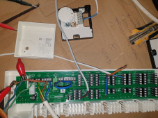
It has a relay and 24V & 24V connections.
Probably you need to supply 24V externally, that is switched by thermostat with rotary dial, and activates the relay.

You can measure continuity through thermostat while adjusting it.
Apply 24V to relay coil, hear it click, measure continuity through contacts.

I would think L and N would never have continuity unless a heating element is attached and the relay is activated.
Without heating element, when relay is activated L would connect to terminal for element.
 
Thank you @Hedges for your input.

In the mean time I have an update.

The controller unit is a 230 V type as are all the components.

I have narrowed it down to a blown fuse which is not replaced.

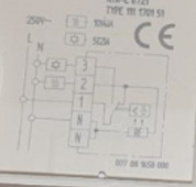
Currently my focus point is on what that wiring schematic means of the thermostat. It looks like I should spit N wire but that goes against my intuition.

So the board works fine for the pump and thermostat. All I need to do now is make sure that the thermostat is wired correctly and then I can test if the actuator valve is being fed 230V when it needs to.

I have already confirmed the valve to be functional
 
@Hedges I meant to say I have already replaced the fuse. Can you please see if you can make heads or tails out of the wiring diagram of the thermostat? IF we can solve that then that would make such a huge help
 
This diagram, from inside lid of the electromechanical thermostat?
I see 250VAC Line going to terminal 1, a moving contact switched between terminal 2 or 3. Those come from two devices shown as icons, one resembling the sun or a Star of David. Other can't make out at all. Also can't read the legend for them. Other side of those icons goes to Neutral. When terminal 2 is selected, an icon inside the box is also powered and has return to Neutral.

1638546769865.png

From the whole picture, it appears the thermostat just switches 2 wires, continuity when temperature drops below setpoint is most likely.
Test the thermostat continuity stand-alone without bigger board connected.

I don't follow why the big board has so many terminals, but only one relay.
I would expect any zone with its thermostat could enable a shared circulation pump plus its dedicated valve, assuming a hydronic heating system.

The board is so simple, you should be able to measure continuity from thermostat to terminals and relay. If voltage applied to relay its contacts should switch. No mysteries like a control IC. (my furnace board has various ICs and a bunch of relays. I found same part number used and swapped it.)
 
Back
Top