• Have you tried out dark mode?! Scroll to the bottom of any page to find a sun or moon icon to turn dark mode on or off!

diy solar

diy solar

Order of ac outlets on branch circuit

Probably easier to just go with the long leaded meter and measure the ohms of the circuit directly then.
 
Probably easier to just go with the long leaded meter and measure the ohms of the circuit directly then.

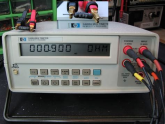
I usually see about 0.5 ohms contact resistance. It'll probably vary from socket to socket. With < 2 mOhms/foot of wire, need a 4-wire ohm meter.

1600315428708.png

Using a separate 12A current source accomplishes the same thing, and gives a signal 10's of mV per foot.

Last time I tried measuring automotive fuses I wasn't getting much resolution with my bench meters, so I used a several amp power supply (with 4-wire feedback) instead, and that worked well.

 
When I refer to a meter with a long lead I am actually referring to a proper test meter for mains wiring testing. My mistake, didn't actually say that in my original post, just 'test gear'. Obviously a standard meter that puts 3V at piddly current across the wire is going to have a hard time of it.
 
When I refer to a meter with a long lead I am actually referring to a proper test meter for mains wiring testing. My mistake, didn't actually say that in my original post, just 'test gear'. Obviously a standard meter that puts 3V at piddly current across the wire is going to have a hard time of it.

Have a link to what those are?

I'm not familiar with them, and a quick search just turns up typical DMM.

Thanks.
 
Don't quote me on this specific model, I'm not a sparky and don't do this stuff myself. It's only from my general knowledge.

 
Don't quote me on this specific model, I'm not a sparky and don't do this stuff myself. It's only from my general knowledge.


Interesting ... not sure if this $2000 to $4000 meter would do what Joey wants as well as the electric radiator heater setup I proposed, but it does estimate prospective fault current up to 50 kA based on voltage and resistance. Appears it measures resistance out the utility lines, through transformer, and back.

It also includes hipot for insulation and ground-fault device tester. Doesn't mention arc-fault, a device required in new house wiring for US.

These pages reference vendor's site in Australia, and mention tests used in the U.K. Here in the U.S. we just slap in wires/boxes and the inspector visually checks them. Maybe the utility does some better tests, also maintenance of industrial facilities.
 
At the time I thought it was more of a 'How could this be done' rather than a practical "I'm going to do this so how should I go about it" question. :)

Installations here have to be checked as part of the job and the job itself can only legally be done by a licenced sparky. There's no run your own wire and get a 3rd party inspector to glance sideways at it and sign off.
 
Probably pointing to the test set a post or two above it, looks a lot like a tone sender used for tracing phone / network cables but set up specifically for tracing mains wiring.
 
It was a 1/4 baked foolish response that was meant to inject humor, and I linked the wrong comment at that. Please just ignore it. I'll show myself out.
 

diy solar

diy solar
Back
Top