diy solar

diy solar

Orion-Tr DC-DC Converter (12v/12v, 20A) as charger?

HelloMan

New Member
Joined
Jul 14, 2021
Messages
11
Hey!

So I know that Victron makes a "smart" version of this same unit, but in my position (college student) the cost savings of going with the straight DC/DC converter is significant. Like...week worth of food significant.

My question is this -- I just built a 105 AH 12v (4S) LiFePo4 pack for my car. Has a good 100A JBD bluetooth BMS with low-temp cutoff etc. Can I use the straight up DC/DC converter which seems to be "dumb" (no charging stages) as a charger? It does have adjustable output voltage, so I assume I would simply set it for between 14.2-14.4V (Battle Born says 14.4) and let 'er cook? I know the BMS will protect from overcharging but...I really don't want to break this thing when I need it to run the diesel heat xD

I have seen Will top off packs with a bench power supply and nothing went boom...I assume this would work the same? The only issue I can think of is you would essentially be floating the battery at 14.4 because I won't be pulling over to shut off charging every time my app says the battery is topped off, and the "dumb" Orion will be sitting, outputting a constant 14.4! Will that be a problem?

If I need to get the "smart" unit, I will, but...food. So trying here first!
 
Running at too high a voltage will cook alright.

That'll overcharge your battery.

If you absolutely insist on doing it this way, then set it for 13.6v or less. That's 3.4v per cell and should not cause any issues with your battery while still giving you a ~99% full charge.

Remember these things spend the vast majority of their discharge curve at about 3.3 volts.

And do make sure the converter is turned off when you shut off the engine to avoid killing your starter battery. You can use a manual switch which you might forget, or spend a bit more and buy a dc to dc charger with ignition sensing that'll protect your expensive gear and eat Ramen for a few weeks.
 
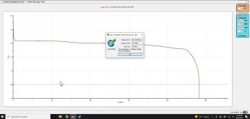
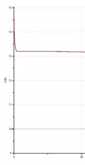
If you're wondering just how much capacity you're "losing" by not being at 14.4v have a look at my most recent discharge test.

Screenshot_20210926-142517.jpg

13.6 to 14.4v is about 1ah for my 240ah pack and will be even less for yours.

Screenshot_20211010-232303_Gallery.jpg
 
Charge from what? The car battery to your LifePo4 pack?
Yes -- I intend to do alternator charging (potentially adding solar down the line). I have an H8 AGM and a 190A alternator, so I just need a way to regulate voltage while not pulling insane amounts of alternator current, especially at low RPM.
 
If you're wondering just how much capacity you're "losing" by not being at 14.4v have a look at my most recent discharge test.

View attachment 68397

13.6 to 14.4v is about 1ah for my 240ah pack and will be even less for yours.

View attachment 68399
Okay -- I follow 100%.

The Orion (even the dumb one) can be wired to the ignition or to any low current switch to power it on/off. That was a basic requirement for me given where the battery is going (buried in the back). I will be pulling power from my H8 AGM starter battery (100AH reserve capacity) so even if something were to so slightly wrong, as long as the auxiliary battery was mostly charged, it wouldn't likely be the end of the world.

My understanding is that most chargers "float" lithium at approx 13.4-13.6 anyways, so you're saying I should simply set it for that and leave it. Not too concerned about the capacity loss, and I assume that might even extend pack life to charge at a lower voltage. Will it impact charging speed much? That isn't a big voltage delta but just thought I would ask.

At what point does the overcharge protection on the BMS kick in? Not entirely sure how that works.
 
Overcharge protection occurs at two points on most systems AFAIK.

If any given cell exceeds the set value voltage or if the whole pack does.

For lifepo4 cell overvoltage cutoff should be at 3.65v and pack overvoltage should occur at 14.6.

Assuming you top balanced properly you should see neither scenario.


Likewise, undervoltage occurs at 2.5v (cell) and 10v (pack). You're far more likely to encounter this on a regular basis.

There are some arguments for doing a bottom balance instead of a top balance but for most people top is fine.
 
Oh.

I will add that you may even wish to set the undervolt cutoff a bit higher to avoid regularly dropping all the way down to 2.5v per cell BUT the better idea is to set a low voltage alarm of 3v and leave the 2.5 in place.

This will give you a bit of time to shut off the diesel heater without damaging the thing. If they cut off while at temperature the lack of fan will overheat the main board and wreck it.

You would also do well to ensure the low voltage cutoff on the heater is set correctly so it shuts itself down completely *before* the bms cuts off.
 
Hi!

Using the victron dc/dc converter to charge LiFePO4 is something that I want to do too! Still mulling over options on how specifically to approach it in my own case.

I personally think you are onto a great idea.

The non-bluetooth potentiometer adjustable one has a "Remote on/off" plugin where it's possible to easily turn it on and off, which could enable charge termination at "full charged" condition and certainly increase cell life as mentioned already.

In device manual
Optional remote on/off: replace the wire bridge on the green connector by a switch (switched current is less than 100mA), or remove the wire bridge and connect the right-hand terminal of the green connector to the battery plus with a switch (this could for example be the engine run/stop switch).
So some tiny relay that can handle at least 100mA continuously ought to enable Arduino Control!

(I have a 12v/12v-9amp Isolated model testing right now. It consumes 2.9 milliAmp across the Remote On/Off terminals with a 9.95V input source)

If you're on board for that sort of thing, happy to help and link tutorials and example code.


So say you want to do this DIY... it's quite doable!

Basically, to save a lot on charging hardware, I would propose you attach an arduino to your system that monitors battery voltage and controls a small Latching Relay to control the Victron DC/DC converter Remote On/Off terminal. This would enable stopping the charge when it's full with complete control in your hands ? this is a higher level of flexibility than even the smart victron expensive stuff.

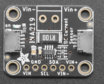
This device has been reliable for me in previous projects for measuring battery voltage: INA219 https://www.adafruit.com/product/904
1633935693458.png
In your case, the Vin+ pin would be connected to the battery Positive terminal. The arduino would attach to this board with the plug on the side, and read out the voltage. It supports up to 26 Volts, so with your 4S LiFePO4 system it should be happy with the 3.65V*4 max.

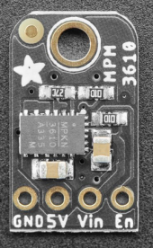
This power regulator will take the 4S battery voltage and regulate it to 5V for the microcontroller input.
1633941422002.png

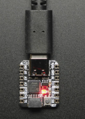
Would plug it into this microcontroller which is 100% compatible with Arduino program. It would effectively replace the "smart" part of the more expensive victron device.

1633935889028.png

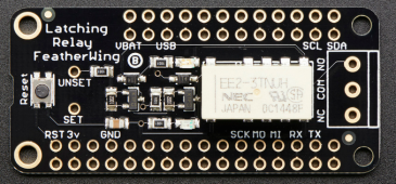
Lastly the Latching Relay to control the Remote on/off port and thus control charging.
1633939585979.png

Basically, connect one pin of the QTPY SAMD21 microcontroller to the UNSET pin. This will turn off the charger/relay. Connect a different pin of the microcontroller to the SET pin and this will turn on the charger/relay.

Then connect the Left Remote On/Off Pin (Positive +) to NO pin on relay. Connect the Right Remote On/Off Pin (Negative -) to the COM pin on the relay.

When you tell the microcontroller to do HIGH on the SET pin and LOW on the UNSET pin, it will Connect the Voltage Input to the Remote On/Off Negative Pin, which will Enable the DC/DC Converter and Begin Charging.

When you tell the microcontroller to do LOW on the SET pin and HIGH on the UNSET pin, it will Disconnect the Voltage Input to the Remote On/Off Negative Pin, which will Disable the DC/DC Converter and End Charging.

This is what I'll be testing soon. Right now waiting on the $10 latching relay.

Hope this helps, sorry if it's a bunch of gibberish. Good luck!

edit: total cost of these parts is 10 + 7.50 + 7.95 + 5.95 = 31.40 usd pretax as of now on adafruit. plus some wire and solder. i might have made mistakes lol but i'm pretty sure it will work. if it does i'll try to share what worked. i'm just an amateur and also don't really know all the options for charging to be honest.

doubly edit: oooops. i’m using the isolated dc/dc converter. it has a remote on/off switch but i just realized the non isolated one doesn’t have that.
 
Last edited:
Before we go too nuts can one of you link this 20a 12/12 *converter* we are discussing?

I can't seem to find it. Only the 12/12 *charger*.
 
for the isolated dc/dc converter (no charging logic, only potentiometer)

(this is the one i’m using)
Victron Energy Orion-Tr IP43 12/12-Volt 9 amp 110-Watt DC-DC Converter, Isolated


(this is the one i erroneously assumed OP was talking about, 404 coffee not found)
Victron Energy Orion-Tr IP43 12/12-Volt 18 amp 220-Watt DC-DC Converter, Isolated


disclaimer: may have messed up the links. it’s a drop down menu for capacities and voltages
 
Woo boys.

Why would you spend so much money on one of those, then an extra 32 dollars plus time and fabbing, when the *smart charger* is only an extra $17 said and done? Plus less components to fail on you later.

Never mind needing the consumable solder and flux, and possibly also a soldering iron lol


I love the diy crowd man but sometimes yall (we, me included) really will spend more money than it costs to just buy the thing outright.
 
one unstated thing that i forgot to mention.

most “chargers” will do a “program” something like “bulk” > “absorb” > “float” which seems to be in part an artifact of lead acid family chemistry.

LiFePO4 does not need “float” from my amateur reading and “float” can sometimes accelerate aging of cell if it holds cells at >3.5 Volt per cell for extended time and especially at >30C. Basically because they hold charge so well that “float” is not needed if there is no big draw

From searching, basically all chargers that are considered to be compatible with LiFePO4 use this algorithm above and require the use of “float”. Many people say to just set float voltage to a low value to “disable it”. Which does indeed seem to work well.

I desire a charge controller that will charge the LiFePO4 cells to 3.5vpc and then stop charging entirely until cells drop to below 3.4vpc or some other arbitrary condition that might include time below voltage or state of charge.

If you can provide a link to a product that will terminate charge entirely at end of absorb, I would be grateful, as that is the specific motivation for this circuitry.

A separate reason is that victron does not include ve.direct wired data port on the bluetooth enabled dc/dc chargers from what I can find, and for my needs a wired data port is required.

tl;dr because most charger logic cannot disable float, only reduce float voltage, and i want all charge to terminate after absorb to reduce time cells spend at upper voltage. also the “smart” bluetooth ones don’t have wired data port
 
oops, also left out, the isolated aspect is also important, despite the associated conversion losses. so my advice is definitely to be taken with some large grain of salt! might be motivated by weird unrelated system goals
 
Why do you need isolation?

99.9% of people don't.

Are you running noise sensitive electronics or are you confusing electrical isolation with chassis/house battery isolation?
 
Oh also "float" isn't an issue. Victron knows well enough to trust their lithium charge profile wrong ruin anything.

As you said though if you insist, just set the voltage low. Done.

You can sit with the thing holding say 13.2 volts for ages. Certainly longer than you should be storing them totally unused for anyways.
Sorry if I gave the impression that using “float” is in any way dangerous or will certainly lead to premature cell failure. That is definitely not the case, it’s totally safe to just configure a lower float voltage.

Using non-standard charging protocols seemed to be on the table, exploring options.

For 99.9999% of people most of these factors just don’t matter, and just purchasing any of the common chargers will work perfectly well ?
 
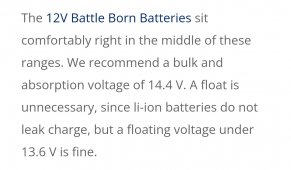
To quote Battleborn;

Screenshot_20211011-055226_Chrome.jpg

Anything under 13.6v is fine. That's 3.4v per cell.
At 13.2v, which is where my wfco converter floats at, it is 3.3v per cell.

That's a non-issue.

You might make the argument that you want the things to last 40 years and that's all well and good, but you'll have less impact with a low float than you will see by ensuring you never charge past 14v or discharge below say 12.8v or otherwise only using 75 or 80% of capacity.
 
Woo boys.

Why would you spend so much money on one of those, then an extra 32 dollars plus time and fabbing, when the *smart charger* is only an extra $17 said and done? Plus less components to fail on you later.

Never mind needing the consumable solder and flux, and possibly also a soldering iron lol


I love the diy crowd man but sometimes yall (we, me included) really will spend more money than it costs to just buy the thing outright.
Whoa, I go to bed and all the fun happens! Stupid sleep.

At least where I am the DC/DC converter (18A) is $54 cheaper than the 20A smart charger. I suppose that savings may not be worth it...though it would be approximately the cost of the wire and other stuff I need to pull this project off. I could tinker with arduinos (thanks for the writeup CuriousCarbon!!) but that would get me very close to the cost of the smart charger! At that point I would just spring for it.

I guess the biggest advantage of the dumb charger is the smaller footprint -- I am very space constrained. The back of a Volvo XC90 has a "hidden" battery compartment and two adjacent compartments for fuse panels etc. to either side of that. That is my working area, which needs to contain my H8 AGM, 105AH LiFePo4, 2KW diesel heater, and DC/DC charger!

Thanks for bringing up the low-voltage disconnect and the heater. Didn't think of that, but I totally agree. I'd hate to foul the heater if I run out of power. I'll work up a low voltage alarm, that is super cheap (like $4) and easy. Thankfully I will only be running the heater when I am in the car. I ski a lot, and I am tired of freezing my arse off and sleeping in a damp condensation filled SUV!
 
Back
Top