diy solar

diy solar

Overcrowded Buss Bar

aaron_c

New Member
Joined
Jun 18, 2020
Messages
210
As I design my system I've realized that my negative bussbar will have more connections than it has posts. The situation:

I was going to use a Maxibus buss bar with six posts. The connections it needs to make:

1) Ground Wire (From Victron Multiplus)
2) DC Negative (From Victron Multiplus)
3) DC Negative (From 12 V Fuse Box)
4) DC Negative (From 24 V Fuse Box)
5) Chasis Bond
6) Shunt-Based Battery Monitor (which then goes to the batteries)
7) Solar input (when I add that...which is not yet)
8) Surge Protector

So I've got six posts and eight inputs on the negative bussbar and I'm not sure what to do about it.

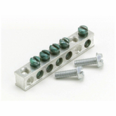
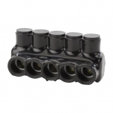
One thought is to use something like this Mofeez Bussbar, but it seems like I have at least four connections that might carry large loads and which probably require a thickish post for the connection, not a connection with a simple screw (is this a thing? Am I making up a problem that doesn't exist?). There are three "posts" on this bussbar, so...maybe not enough? Or could I double up the DC negative and Ground Wire from the Victron on a single post?

Another thought is to just keep using the Maxibus and double up a few connections. Is this a problem?

I'm just not sure what I should be doing. Thoughts?
 
While it's generally not a good idea, you could double up some of the connections with low current draw.
 
I'm willing to spend a bit more money for the right bussbar...but all the bussbars I've seen either have smaller connections (like with a screw) or not enough posts. Am I missing something?
 
Sometimes I put a single wire through a lug, use both ends of the wire for connections.
I also use split bolts to splice wires.

Bob B mentioned current draw - surge protector won't normally carry any current, neither ground for Victron, nor chassis unless you use it that way.

you could also add a bus bar called "chassis" and use it for ground, with a strap to negative in this box.

"not a connection with a simple screw" You should see the 6mm screws Lithium battery guys are using to clamp high current busbars.
My greater concern is when a wiggling or expanding wire can loosen a screw. And that stranded wire doesn't seem to compress all the way at torque specs for terminals. I wiggle them a lot and re-torque until they stop settling.
 
Last edited:
I have sometimes also put more than one wire in a terminal connection. The important thing there is to make sure the terminal connection is sized such that you can get a good crimp.
 
Thanks @Hedges, good information! I'm so happy I have the folks here to tell me about little details like wiggling the stranded cable around a bit to make sure it settles.

OK, so it sounds like I can probably combine the DC ground, Chassis Bond, and Surge Protector all together. Since none of them should have any current if things are going right (and since hopefully only one thing will go majorly wrong at once) that should be safe? Or should I distribute those "usually no current" lines amongst the bussbar?

And going with what Hedges said, I'll stick with the bluesea bussbar since the nuts/bolts are less likely to wiggle apart.
 
That sort of busbar requires ring terminals. It is convenient to put wire ends under a screw.
Maybe one of these could be mounted on the Blue Sea, consuming two studs or getting tapped holes:

1601648248658.png

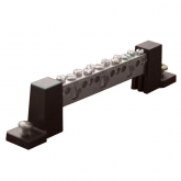
Some of the combiner boxes have them with insulating standoffs, could be connected to first bus with a wire:

1601648384572.png

I've also used these:

1601648499817.png

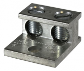
For multiple taps of my AC hot and neutral, fanning out to breaker boxes and disconnects, I use these:

1601648675381.png
 
You could combine all the 'green' ores on one terminal. Or larger buss bars are available. here is one overkill. https://www.bluesea.com/products/2107/PowerBar_600A_BusBar_-_Eight_3_8in-16_Studs__
I personally have two negative buss bars. They do connect together.


Continuous Rating
information.png
545A AC
600A DC

Can Blue Sea really measure something that matters with 10% difference in current?
Or is that applying ampacity calculations and skin depth at 60 Hz?
 
Those "screw clamp" type connections are not near as good as crimped terminals. Especially with stranded wire as should be used on mobile applications as the OP's trailer.
I would trust Blue Sea for how they rated their products. Very much more than I would trust a random supplier on Amazon. Or such an internet expert such as I. Blue Sea employs qualified engineers. Blue Sea must meet strict standards for their products to be used in the marine industry. It may be overkill for my vans, but I sleep better knowing I am providing a safe build. I don't think "skin depth" is a factor at such a low frequency as 60 hz. 9%
 
Large gauge crimpers apply several tons of force, which people here have shown by cross sectioning turns stranded copper into something solid with no air space in between. When I use a torque wrench on set screw wire connectors like for 200A AC circuit breakers it doesn't do nearly that much. I find that by moving the wire around, the strands settle and screw can turn further with the same torque. I've heard of people periodically re-torquing connections for something they wanted to ensure was reliable, an elevator (but they stripped the threads and just kept spinning the set screw.) My AC panels are full of set screw connections. The only ones that aren't are where main lugs or breaker bolts to busbar, and where multiple neutral bars tie together.

So maybe that's the big difference with crimped ring terminals vs. screw terminals. Screws could have been designed with sufficient strength but aren't.

Torquing connections:


So it seems like making quality crimped ring terminal connections and using torque wrench on a busbar like Blue Sea is a good way to go. We would really have to go out of our way to conduct full load tests and observe heating of our connections to determine if they are adequate.

"At 60 Hz in copper, the skin depth is about 8.5 mm"
That means at the center of a 17mm diameter wire, current is 1/e or about 1/3 what it is at the surface.
Just enough to start influencing ampacity of large conductors, up around what's used for 200A or so.

 
I bet the ampacity charts take that into consideration. Skin depth would be the whole of 17 mm, 8.5 from all directions. That is much larger than 4/0 cable. 4/0 is less than 12 mm diameter. So I would guess no effect at 4/0. I have no 60 hz ac current needing that large of wire.
 
Yes, they do. Skin depth and surface area of insulation which is in the thermal path.

Skin depth does have an effect for 4/0, its just that current in center isn't reduced that much.
Radius of 4/0 is 5.84 mm, so current at center is exactly 50% of current on surface.
Only a moderate effect, since much more of the cross-section is closer to the surface.

But then we actually have to evaluate E-fields. Consider a PCB trace, rectangular cross section over a ground plane. In that case, most of the current is flowing on the bottom surface of the trace, because E-field is strongest where close to the plane. That is typically high frequency, and skin depth is mils to microns. For a bundle of 4/0 cable and 60 Hz, I'm not sure to what extend current flow and skin depth is measured from where wire faces the other wire carrying return current, and to what extent it spreads over the entire circumference.

For Coax, they symmetry makes the problem easier to write equations for and solve.
 
Again I may use 60 hz power with 2/0awg when at anchor on the dirt. I do not worry over the nitty-gritty details of higher electronic theory with my limited 120V van system, or even the tool and die shop I sometimes apprentice. It doesn't enter any calculations sizing out the dc side of life. I don't plan to ever climb a power tower again. Avoid the Army.
 
I know the pointy heads in the EE world have to have things just perfect. But in the real world I have all my DC components, except my inverter, all tied together stacking ring terminals on a bolt all squished together with a nut and have never had a problem. My largest load is a water pump that will only draw up to 20 amps for a few minutes though.
 
Back
Top