i like it better,easier to make my own length of cable.Have you used the bolt holes on this BMS and did you find bolts and lugs as good as a soldered connection? Thanks much for any info here.
bolts down nicely.
seems to work just fine.


i like it better,easier to make my own length of cable.Have you used the bolt holes on this BMS and did you find bolts and lugs as good as a soldered connection? Thanks much for any info here.
Thanks much. What type of wire and nuts and bolts did you wind up using? What AMP BMS did you have? I found that 10-32 nuts and bolts fit well.i like it better,easier to make my own length of cable.
bolts down nicely.
seems to work just fine.
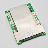
If you're looking for this, Amy Wan mistakenly sent a photo of the JBD 3.7v when confirming my order.Sexy!
When will these be available for 3.7V chemistry?")
Just Don't Do this. This is what happens if you over load the wire and do not have the correct fuse to protect the wire.Hi all
I am building my first battery and have this 48v/100a BMS and 16 EVE 280ah cells.
My intention is to connect to a Victron Multiplus II 48/5000 using the driver from @Louisvdw.
I have the battery bank all wired up with the BMS and everything is as expected. Now to connect to the Victron. The Victron manual says to use 70mm2 cable and a 200a fuse. The cable on the BMS is 2 x 10mm2 cable. I was going to use a 100a fuse.
I presume this is because the Victron is capable of more than the 100a my battery is going to provide?
I was just concerned that the cables on the BMS seem a little thin!
Does that all seem correct (and more importantly, safe)?
Thanks
Just Don't Do this. This is what happens if you over load the wire and do not have the correct fuse to protect the wire.
Hi all
I am building my first battery and have this 48v/100a BMS and 16 EVE 280ah cells.
My intention is to connect to a Victron Multiplus II 48/5000 using the driver from @Louisvdw.
I have the battery bank all wired up with the BMS and everything is as expected. Now to connect to the Victron. The Victron manual says to use 70mm2 cable and a 200a fuse. The cable on the BMS is 2 x 10mm2 cable. I was going to use a 100a fuse.
I presume this is because the Victron is capable of more than the 100a my battery is going to provide?
I was just concerned that the cables on the BMS seem a little thin!
Does that all seem correct (and more importantly, safe)?
Thanks
Not completely trueAlso the shorter the cable then more current it can do.
TrueSo try and keep the cables short will always be better.
So is this chart referencing Distance or Voltage Drop? Obviously both, but it appears to indicate there is a relationship between distance, Amps and wire size, as though a smaller AWG wire could be used for the same amp at shorter lengths. Not trying to challenge, a sincere question.Not completely true
True
My understanding:
Voltage Drop becomes less and less of a factor the shorter the cable. So in that sense, the shorter the cable the more current it can handle for a given voltage drop. But voltage drop is just one of two factors to consider, and not the most important one from a safety standpoint. The Ampacity of the wire is not relative to length (its relative to insulation temperature rating, ambient temperature and other factors), using shorter wire does not allow you to exceed the ampacity limits of the wire, and for high current short length wire runs like a typical inverter circuit, ampacity is often the limiting factor not voltage drop.

So is this chart referencing Distance or Voltage Drop? Obviously both, but it appears to indicate there is a relationship between distance, Amps and wire size, as though a smaller AWG wire could be used for the same amp at shorter lengths. Not trying to challenge, a sincere question.
View attachment 77031
So is this chart referencing Distance or Voltage Drop?
I think possibly I wasn't clear in my last comment. Let me try to rephrase, and then I will give an example or two.Obviously both, but it appears to indicate there is a relationship between distance, Amps and wire size, as though a smaller AWG wire could be used for the same amp at shorter lengths.
A shorter round trip distance = lower total resistance in the circuit, which means you can get away with a smaller wire size for the same amount of current. BUT only up to a point. The point at which ampacity becomes the limiting factor, not voltage drop. For long wire runs voltage drop is almost always th limitation, but for short distances ampacity can be the factor that determines wire size."there is a relationship between distance, Amps and wire size, as though a smaller AWG wire could be used for the same amp at shorter lengths."


Great thanks. Explains why I was seeing such wildly different wire sizes from calculators last fall when I was designing an off grid system. I was seeing small wires recommended that I knew by instinct, "there just ain't no way"I think possibly I wasn't clear in my last comment. Let me try to rephrase, and then I will give an example or two.
Voltage Drop IS dependent on distance.
Ampacity ISN'T dependent on distance
Both Voltage Drop & Ampacity need to be considered when sizing the wire.
So proper wire sizing considers one factor that is distance dependent and one factor that is independent of distance.
The practical takeaway is that, up to a point, its exactly as you wrote:
A shorter round trip distance = lower total resistance in the circuit, which means you can get away with a smaller wire size for the same amount of current. BUT only up to a point. The point at which ampacity becomes the limiting factor, not voltage drop. For long wire runs voltage drop is almost always th limitation, but for short distances ampacity can be the factor that determines wire size.
It will be safe following a chart like the Blue Sea chart or calculator, since it does consider both ampacity and voltage drop (without explicitly showing it), but many charts and calculators are only voltage drop calculators and do not consider ampacity. This is something to watch out for.
As an example, lets consider a 2ft circuit with a voltage of 48V and a max current of 200A, lets target <3% voltage drop.
The example I chose is extreme, and designed to underscore the importance of considering both factors, and sizing the wire based on whichever factor is the limiting factor for the given variables.
- A calculator that considers only voltage drop would suggest that 12AWG is acceptable for this short of a distance. Even though the maximum safe limit for premium 105*C rated 12AWG wire is <45A ,and our example is a 200A load.
- However a calculator that considers both ampacity of the wire and voltage drop would recognize 200A through 12AWG would be insane and would suggest 2AWG as the minimum size. Even though 2AWG would only be a miniscule 0.13% voltage drop, well below our 3% target.
The Blue Sea chart below, doesn't explain this (or the other assumptions it makes), but it does consider both factors:View attachment 77031
If you look at the bottom of the chart, it references "ABYC E-11". This is the marine standard that the Blue Sea chart is derived from. It comes from (among other things) crosstabulating the ABYC E-11 Voltage drop table for 12V and the ABYC Ampacity table for 105*C wire, in free air, at less than 30*C
Here is an example of the ABYC voltage drop table and the ampacity table for single conductors that underlies the Blue Sea chart/calculator:
The Bay Marine Wire Size Calculator and the Blue Sea Circuit Wizard are two that I know take into consideration both voltage drop and ampacity. There are still variables you have to consider and be aware of (As an example they assume 105*C rated high quality marine wire which is common in the marine world but cheap wire from amazon will probably have a lower insulation rating).Great thanks. Explains why I was seeing such wildly different wire sizes from calculators last fall when I was designing an off grid system. I was seeing small wires recommended that I knew by instinct, "there just ain't no way"