diy solar

diy solar

Overpaneling Renogy DC-DC w MPPT (updated with circuit diagram)

grncdr

New Member
Joined
Sep 11, 2022
Messages
5
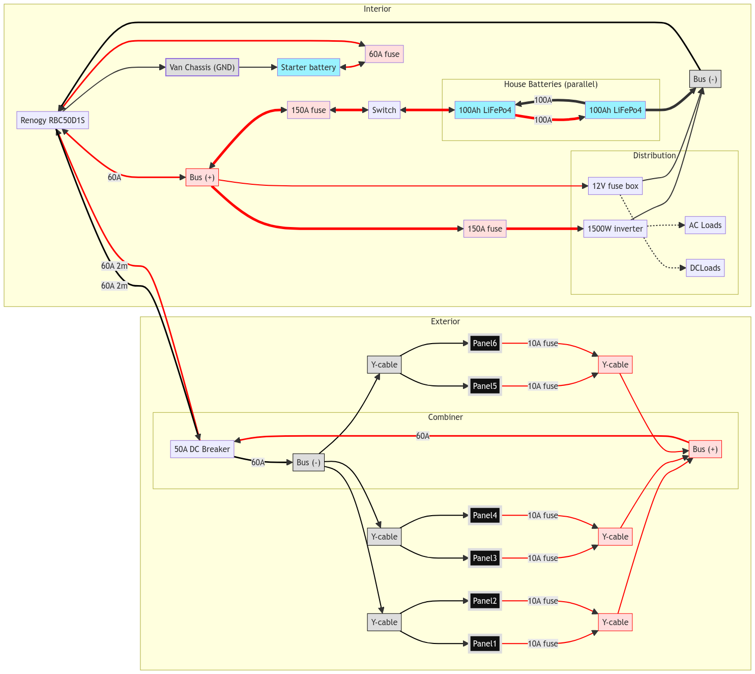
I'm looking at putting the 50A Renogy DC-DC MPPT (RBC50D1S) in a van that has 6x120W (2S3P, all Y-adapterss) panels already mounted. The panels themselves have a Vmp/Voc of 18v/21.6V, so I intend to rewire them as 1S6P to stay under the 25v max PV limit. The Renogy datasheet states a max solar input power of 660W, as far as I understand it, that means I'm missing out on a theoretical ~60W in ideal conditions. Because conditions are rarely ideal I think the overpanelling isn't too extreme. Please tell me if I'm way off here.

My first question is: what current from panels->charger should I be designing for? The panels themselves have an Isc of 7.72A, so as far as I can tell the Renogy could never pull 50A from the panels under non-fault conditions. Would a 50A breaker (and corresponding cable gauge) between the panels and charge controller be appropriate? Could I go even lower?

I want to combine the 6 panels before they ingress to the van, but this means weatherproof connections. It seems like there's no MC-4 y-adapters rated to 50A, not to mention the difficulty of attaching an appropriate sized cable to the connector. Does anybody know of a solution smaller than a DIN rail in a residential "combiner box" that I can safely use?
 
Last edited:
After searching more threads and reading the excellent guide to fusing from @FilterGuy, I now have the following circuit diagram:

pako:eNqFVm1v2zYQ_iuEAhQddg5EUpIltSgQ2-tWoCuCBEjRxvtAW5QjRJYCWU7jBfnvI0VSol6M-YP5cs89dzzeHfXqbMuEO7Gzq9jTA_p6sy6Q-F2Xhx_4fu38mG3ZJudr559un5zZpxP73_hukkfukzP7UzzLcr_JCl4JO0K6OB7Q-99_G0mFtpHOOun13aLi7JFX9757hVZLpJdG-YEdDpmkvWOFWaH3f35bdRS3NatqXn0-HrjABYImFdNGrABfimcuEffYd93vKNPLzkS1E8IbXpS7E7pZLH13hW_75AtWi_-T4NcbaKN2lJl6Xf_NskK7gH3bB9uDswCpLUIzHUEtnA7gailJF-WL5CV3DS3alC-tYwqmYnE4blQq_fEivMnKSkHabXNXSqd3s5qstq7TbLV3qNR4kZjIX7OC5xi9UxOCZjMkvGwPL9afVDZbcGrg3lk4seC-gQdn4dQqG4mWDHqkDah3zLYylH7_BFaBdOLOY6tOOnHn4aggGpAy9k6zqpGaCFquyfPJ7G6I-yFvlzamd1P6Utqb_lKYBLBqoJ-sXfLJDNPl8Curtw92Sk0YJ3tl3ybViwFkcIypkkMfJdCqcbXRI-_1CmThNcfQhU8G2xd8tILXFaSyZ8Kg3WnCoObaBlbVoFfEJjEX3fo8rPlGaveI3kb_VgbEk1RtTxiBFbzNgrXzVynNKa8zLlrLE6tYnvNcdBjTBcwJZYdx3SvxEGWf-XXptT2ohZD_h8iyQhKDrOCRIc8UCFvtRaVf17hW2aGuss2xzspiGK9LQXG1FJ5dLdHXkiWHce9UoNVSiQtjxepkclSzbS5SZ8VT9CRrGqVZnscXGGPYlnlZxRdpmoJwpnzk8UWSJHo--5Ul9UPsf7BIdHMB1VrUQNXgqcEH3doaWyMP9BukfYiilKRpz4CJHJi4wqC4zCs2ZG5eEUWbpkmaJD1aUwxglSXY-avcxt2UdFPaTb1u6nfToKmApocP3XoWHwHKq1FkSc9D0wuEwvjeykNWZ89cvqT6iC2ZPK4rfh8GOgXfsb5OYum47lDHqkiwWjg0b1DzT0C9P5Y3E_qiaMHq49C8Fc0_AfXMWJ6Zk-ZZ8Xhbn3KOXMBAgIIHPgQwhxBplytubrQDR4AFHgMmgClgD7APOAA8N0qbnG0fR2o4BOICIUAokMAy0L8fOlaMgGCguEc_VhqqUReoOcegqjoQmQMRfkVAxfEp0PlAAXpxkI3bMuD3o-SAs-fVnmWJ-BJ_lZbWTv3A9-ITIxbThKfsmNeyXb4JKDvW5e2p2DpxynKR0s7xKWE1X2VMdKp9uysK2olfnRcnxtFl5IVzSug8cKMwEO46Jyem3mVESDj3PN8NQupH3hs4_5aloHAvw8BzI9ebeyENhWrY8P1shHV15G__AY3Y1jE

(source)

I like this because now my exterior combiner box only needs to combine 6 inputs instead of 12, allowing it to be much smaller. I also already have the Y-cables on hand.

I still have one question about fusing. As I understood it, 2 panels in parallel don't require a fuse. Could I treat each pair of parallel panels as single panel and replace the six 10A fuses with three 20A fuses on the output of each Y-cable? It would save a few more connections (and €), but that might be a false economy.
 
Last edited:
Stay away from renogy if you want it to work. I have several renogy products and have issues with everything they produced. The DCC50S unit has to have solar disconnected at times for the vehicle side to work. Renogys fix and it does as needed. I tried to get a refund for all my products but they said it was past the 90 day point of ownership for all but the one M1. On my 3rd unit and it now says invalid serial number. I'm done with renogy.
 
I was going to say that you don't need a fuse between two panels. You do need a fuse between the Y connector and the bus. So three fuses instead of six. But the way you have it set up, I'm not so sure.

You might want to look into a 6-into-1 MC4 connector so you have a single connector on each pos/neg side. If you do it that way, the you DO need six fuses.
 
so I intend to rewire them as 1S6P to stay under the 25v max PV limit.
I'd say this is reason enough to avoid this charger. Wiring 6P is ridiculous in my opinion. 42A is too much for most MC4 connectors and Y cables, possibly your solar wire too.
 
I was going to say that you don't need a fuse between two panels. You do need a fuse between the Y connector and the bus. So three fuses instead of six. But the way you have it set up, I'm not so sure.

You might want to look into a 6-into-1 MC4 connector so you have a single connector on each pos/neg side. If you do it that way, the you DO need six fuses.

I think a 6->1 MC4 connector doesn't exist, for the reasons mentioned by @MisterSandals, the amperage gets high enough that you need a fatter cable than what most (maybe all?) MC4 connectors can support.

About "Renogy sucks", I've read quite a few positive reviews in other threads here, but after pricing out the cable runs for the 12v system above, it doesn't look like much of a cost savings over a separate DC-DC charge controller and a 24v system.
 
a van that has 6x120W (2S3P, all Y-adapterss) panels already mounted.
I reread from the top and noticed this as the existing system.

Just out of curiosity, what is the existing SCC and why are you looking to replace it (as opposed to just adding a DC-DC charger)?
 
I reread from the top and noticed this as the existing system.

Just out of curiosity, what is the existing SCC and why are you looking to replace it (as opposed to just adding a DC-DC charger)?
Existing SCC is cheapo PWM controller, and the system is 24v (batteries are currently wired in series). I want to add DC-DC charging and I thought I might kill 2 birds with one stone by picking up the Renogy. When I started adding up all the cables and connectors, it didn't seem like such a good deal after all (even without the potential quality issues of the Renogy).
 
Existing SCC is cheapo PWM controller, and the system is 24v (batteries are currently wired in series).
There are worse solutions. Does it work?

If so, I'd consider just adding a DC-DC charger. I've done this for a friends ProMaster (Transit?) with a Victron 30A model (she considered the 18A model but wanted more charging). Its spendy but should be mighty reliable (5 yr warranty is darn nice too). Then down the road when your PWM isn't cutting it or dies, swapping in a new SCC (MPPT would be nice) should be easy.
 
6-into-1 MC4 connectors do exist. Crazy, right? For the reason that MisterSandals posted, it doesn't make sense. Exceeding the amperage of the connector is bad mojo.
 
You DONT use that Renogy combined Dc DC and MPPT box.....

1) if there is only a DC DC connection you can get the entire 50Amps... The minute you connect ANY Solar and use the MPPT connection the DC DC side is limited to 25A regardless of if there is only 1A applied to the MPPT terminals....

2) if you disconnect the DC DC side and only apply Solar You can get the full 50A through the MPPT....

Its a bizarre design that should be killed off.... Just use separate chargers for DC DC and MPPT.
 
Back
Top