• Have you tried out dark mode?! Scroll to the bottom of any page to find a sun or moon icon to turn dark mode on or off!

diy solar

diy solar

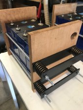
Pack / Cell compression Optimized By Using Springs.

I just downloaded the newer datasheet for EVE LF280K cells from June 2023 from here (thanks). On these cells, Eve applied a clamping force of 300 kgf for all tests. Elsewhere in the document (section 4.4.2), they describe a minimum of 3000 Newtons (roughly the same value, with gravity at sea level) as the minimum, 7000 Newtons as the maximum value of the 'recommended' range. That minimum is 661 pounds. The dimensions of the large sides are 204.6 "height" (excluding the terminals) and173.3 "length" sideways, an area of 35457.18 square mm. That's 54.96 square inches. The 661 pound force is 12.0 PSI, and that's the minimum recommended value.

They used clamping plates of 10mm thickness (almost .40 inches), with 6 bolts applying clamping force (not just 4). They used bolt size M8 (not M6), although M6 or 1/4 inch steel rod can probably also handle a tensile force 110 - 180 lbs per rod without breaking. In my previous 4S battery pack builds with smaller cells, I have used 1/4" steel plates (insulated) to apply lower clamping forces, and I saw those plates begin to warp when I the compression springs all the way in.

I have already purchased 1/4" compression plates for my new LF280K battery pack, but I will also be adding add 3 segments of horizontal L-Bar across the plates (on the plates, underneath the springs) to reduce the tendency of my thinner plates to warp. (Pictures coming after the parts arrive.)

NEW NOTE 2024-07-07: I have built an effective containment for these cells at relatively low cost, applying 720 lbs minimum pressure. That thread is at
https://diysolarforum.com/threads/r...containment-for-eve-cells-lf280k-lf304.78285/
 
Last edited:
I just downloaded the newer datasheet for EVE LF280K cells from June 2023 from here (thanks). On these cells, Eve applied a clamping force of 300 kgf for all tests. Elsewhere in the document (section 4.4.2), they describe a minimum of 3000 Newtons (roughly the same value, with gravity at sea level) as the minimum, 7000 Newtons as the maximum value of the 'recommended' range. That minimum is 661 pounds. The dimensions of the large sides are 204.6 "height" (excluding the terminals) and173.3 "length" sideways, an area of 35457.18 square mm. That's 54.96 square inches. The 661 pound force is 12.0 PSI, and that's the minimum recommended value.

They used clamping plates of 10mm thickness (almost .40 inches), with 6 bolts applying clamping force (not just 4). They used bolt size M8 (not M6), although M6 or 1/4 inch steel rod can probably also handle a tensile force 110 - 180 lbs per rod without breaking. In my previous 4S battery pack builds with smaller cells, I have used 1/4" steel plates (insulated) to apply lower clamping forces, and I saw those plates begin to warp when I the compression springs all the way in.

I have already purchased 1/4" compression plates for my new LF280K battery pack, but I will also be adding add 3 segments of horizontal L-Bar across the plates (on the plates, underneath the springs) to reduce the tendency of my thinner plates to warp. (Pictures coming after the parts arrive.)
I built a 300kgf clamping fixture for my older-generation 280Ah EVE cells but that was nominal with a minimum something below that (200Kgf?).

For the LF280K cells EVE is now saying that 300Kgf is the minimum force to be applied when the battery is fully depleted and as long as the maximum force at full charge is no more than 700Kgf.

I get nowhere near 2X the force at full charge so if I calibrate my clamping fixture for 300Kgf at lowest SOC% (I am bottom-balanced so can get all the way down to 5% SOC), the force near 100% SOC (realistically 90% SOC) will be well under 600Kgf, probably even under 500Kgf).

Did Eve indicate anything about the impact of clamping at under 300Kgf at say 150Kgf versus clamping to 300Kgf at ~0% SOC?

My takeaway from this is that while the old guidelines focused on 300Kgf near ~50% SOC and then provided some general guidelines about minimum and maximums, they are now specifying a full 300Kgf at the minimum SOC and further specifying that springs should bd chosen to limit the maximum force to no more than 233% at full SOC…

It’s a much clearer spec.

Next time I break down my battery for service, I’ll plan to calibrate for 300Kgf at lowest SOC%…
Let me clarify a a couple of bits: They specified the 300 kgf clamp to be applied at SOC between 15% and 40% (not at "fully depleted" SOC, and not as low as you plan to push your cells). 15% SOC is already near the minimum limit which many of us try to enforce via BMS tuning, even though EVE ran cells to the bitter end (2.50 volts, zero percent) in their capacity tests.

I agree with you that the maximum force should not reach anywhere near 700 kgf in a properly built spring loaded clamp: The springs should not bottom out "solid" or have such a high rate (lbs per inch) that the resulting increase in force becomes anywhere near 700 kgf if the springs have been chosen properly. But the total decrease in spring length, cuased by cell expansion, varies with the number of cells in a row - the change in total thickness of my 4S "12v" battery packs are only 1/2 and 1/4 as much as total change which would occur for 8 or 16 cells arranged in a single row (respectively). I can imagine the force on cells in a 16s "single row" arrangement to be doubled, under high SOC and temperature - and I'd be incllined to construct such a "48v" battery pack as dual rows of 8 cells, to reduce the amount of movement near the ends of the rows.
- - -
Eve did not say anything about the expected results of insufficient clamping forces, I assume that they would be more serious (over time) when large variances in cell thickness are "allowed" by smaller clamping forces, and with frequent changes in SOC and temperature. In my own application (living space with in a travel trailer, SOC held between 14% and 98.5%, top balancing only from 96% upwards) I SWAG that the 8000+ cycle life might be degraded to only 2000-3000 cycles - a degradation even worse than operating at high temeratures all the time.
 
Last edited:
Let me clarify a a couple of bits: They specified the 300 kgf clamp to be applied at SOC between two 15% and 40% (not at "fully depleted" SOC,
An even more precise spec - thanks.

Whatever the recommended minimum clamping force that was recommended for lowest SOC, I applied that at about ~20% SOC.

So sounds like next time I am there, I should just apply the full 300Kgf…

and not as low as you plan to push your cells). 15% SOC is already near the minimum limit which many of us try to enforce via BMS tuning, even though EVE ran cells to the bitter end (2.50 volts, zero percent) in their capacity tests.
I never drive my cells under 20% SOC under normal use. But since they are bottom balanced, I can push down to 15%, 10% or even 5%. I’ll generally do this once or twice a year just to let my active balancer improve the quality of my bottom balance…

300Kgf calibrated at 15-20% SOC seems like the way to go (for us bottom-balancers…).
I agree with you that the maximum force should not reach anywhere near 700 kgf in a properly built spring loaded clamp: The springs should not bottom out "solid" or have such a high rate (lbs per inch) that the resulting increase in force becomes anywhere near 700 kgf if the springs have been chosen properly. But the total decrease in spring length, cuased by cell expansion, varies with the number of cells in a row - the change in total thickness of my 4S "12v" battery packs are only 1/2 and 1/4 as much as total change which would occur for 8 or 16 cells arranged in a single row (respectively). I can imagine the force on cells in a 16s "single row" arrangement to be doubled, under high SOC and temperature - and I'd be incllined to construct such a "48v" battery pack as dual rows of 8 cells, to reduce the amount of movement near the ends of the rows.
I’ve got a single row of 16 280Ah cells and once the pack has settled in (over 5-10 cycles),the total travel I get is minuscule - less than 1/8” total between my depleted SOC and my highest SOC.

Since my 300kGf springs can accomodate more than 1/2” of travel within +/-10% of 300Kgf, it’s a non-issue…
- - -
Eve did not say anything about the expected results of insufficient clamping forces, I assume that they would be more serious (over time) when large variances in cell thickness are "allowed" by smaller clamping forces, and with frequent changes in SOC and temperature. In my own application (living space with in a travel trailer, SOC held between 14% and 98.5%, top balancing only from 96% upwards) I SWAG that the 8000+ cycle life might be degraded to only 2000-3000 cycles - a degradation even worse than operating at high temeratures all the time.
Is the new spec for the LF280K with correct clamping force now 8000 cycles???

That’s 22 years to 80% capacity…

I suspect calandra aging will reduce cell capacity under 80% before then,
 
..... 300Kgf calibrated at 15-20% SOC seems like the way to go (for us bottom-balancers…).

I’ve got a single row of 16 280Ah cells and once the pack has settled in (over 5-10 cycles),the total travel I get is minuscule - less than 1/8” total between my depleted SOC and my highest SOC.

Since my 300kGf springs can accomodate more than 1/2” of travel within +/-10% of 300Kgf, it’s a non-issue…

Is the new spec for the LF280K with correct clamping force now 8000 cycles???

That’s 22 years to 80% capacity…

I suspect calandra aging will reduce cell capacity under 80% before then,
Your plan (to re-calibrate to the minimum 300 kgf at 15-20$ SOC) seems perfect, although I would add additional force to account for issues or of accuracy in my spring force calibration process. To the extent that their Engilish words (they provide the translaqtion themselves) are well-chosen, they are trying to recommend a minimum of 300kgf, with a substantial range for "higher but still safe and beneficial" compression values also RECOMMENDED, and not merely allowed. Why not target 320 kgf instead?

The working length of your springs (between uncompressed at "completely flattened") is more than 5 inches? My springs are are much shorter, with a fairly high rate (of additional pounds applied per additional inch of compression). 1/8" of movement by my cells would move each spring from about 110 lbs to around 145 (nearly 900 lbs total, up from 660), because my spring rate is nearly 300 lbs per inch. But of course, with only 4 cells in the row I never see even 1/16" change in the distance of the outside cell faces - and 900 lbs of total force would still be within the recommended range anyway.

They DID specify 8000 cycles as the test requirement - but don't forget, they also adjusted charge and discharge rates downards at extremly high and extremly low SOC (voltage) values, and your charging system is probably not able to make those adjustments.
 
They DID specify 8000 cycles as the test requirement -

8000 cycles / 1c / 2 directions / 365 days = 11 years.
[edit: left out 12 cycles per day, except JustGary said it's 0.5c and half hour rest. 4.8 cycles/day and 3.4 years]
Most [electronic] life tests are done with an accelerating factor. Can be load or temperature. [maybe none for batteries]

Wonder what the source of their data point is.

but don't forget, they also adjusted charge and discharge rates downards at extremly high and extremly low SOC (voltage) values, and your charging system is probably not able to make those adjustments.

What range of SoC supports the 0.2c to 1.0c people might typically do?
Can charge voltage settings avoid going higher than max SoC which supports that?
 
Last edited:
8000 cycles / 1c / 2 directions / 365 days = 11 years.
They specify continuous cycling, not daily, so their cycles take roughly 5 hours (~two hours charge, rest a half hour, ~two hours discharge, rest a half hour), or 4.8 cycles per day. That's 6,000 cycles in about 3.4 years or so. The cycles are a 0.5C, not 1.0C.

Yes, they say you should get 8,000 cycles but the test says to cycle 6,000 times (3.15.1d).
Yes, the test procedure called for only ~6000 cycles with short rest periods, although the specification says 70% energy retention after 8000 cycles. The power rate for charge and discharge within each cycle was varied to even lower watts as the test battery cells become worn. I assume that the verification at the end of their test showed somewhat more than 70% energy storage capability remaining, they possibly used assumptions and historical graphs of earlier versions leading to the 8000 cycle figure.
 
Last edited:
What range of SoC supports the 0.2c to 1.0c people might typically do?
Can charge voltage settings avoid going higher than max SoC which supports that?
They did not test higher charge rates in the in cycle tests, but they did test discharge "energy efficiency" one time, comparing the .5c result to a 1.0c rate (896 watts). Their document only reduced the limits only in relation to lost capacity as the test cells became worn out: SOH limits, not SOC limits as I misstated in my earlier post.

I did not see a particular value required for the cell under the 896 watt test (1.0C), which was run all the way from 3.65 volts down to 2.50 volts. My own BMS is set for lower maximum voltage and higher minimum voltage. I have a personal SWAG that discharging @ 1.0C for extended times, over many many charge/discharge cycles, is probably bad for overall lifespan, but they didn't list a product requirement or test for that kind of usage over multiple cycles.
 
Last edited:
Thanks for this thread and this forum, much useful information. :)

My previous energy storage was using Enerdel NMC cells, 14S about 20kWh. Now I'm changing this to 32pcs of LF280K (from Docan).

Here's the first 16 cells clamped:

1730189280888.jpeg

I'm using Chevy LM7 valve springs. :) I bought a full set (16 springs) for 20€, and I only need half of them. They also included the "cups" that make it really easy to fit M8 screw and nut without using any washers.

1730189417457.jpeg

Here's my test setup for the springs. Exactly 75kg when compressed from 55mm "idle length" to 37mm. It's really easy to check all the springs with this kind of drill setup, as the maximum depth can be locked in the drill.. So lock it once, then try out all the springs to see if they match.

There's only half of my batteries in this setup now, so I will be building another set next to it and connect them in series. I somehow thought I'd only need four of the steel L-brackets, I was surprised when I ran out of material after building this first set. :D

I plan not to top balance, as it would probably take weeks or even months with my 6A supply, and I'm slightly worried of the possible overcharge when reaching >3.4V.. The datasheet says charging should be stopped when current drops below 0.05C @ 3.65V, but 0.05C from 560Ah is 28A! So there is no way to know when the batteries are full when charging at lower amps. I have read horror stories of bulged batteries during top balancing and I believe overcharging is the reason?

I measured all 32 batteries and they are all at 3290mV +-2mV, pretty damn close! I know the voltage gap widens when they reach >3.4V but still I'm confident my 1A active balancer will manage. And I can start with lower top voltage in the inverter settings, so that highest cell only barely reach 3.4V.
 
I did mine with springs that I ordered them from a reputable spring maker, so there was no need to figure out the spring rate, but this is an interesting take on how to check them for sure. I thought valve springs where rated by their spring rate as well, no?
 
I did mine with springs that I ordered them from a reputable spring maker, so there was no need to figure out the spring rate, but this is an interesting take on how to check them for sure. I thought valve springs where rated by their spring rate as well, no?

Yes, valve springs strength is usually given as kg/mm (or lbs/inch) "spring rate", or directly "150kg at 30mm compression".. I think almost all valve springs are strong enough for our purpose, doesn't matter which engine. And used springs are fine, they don't really loose much of their capabilities over time.

Car builders commonly use similar setup to test the spring rate, so this isn't really my innovation at all. :)
 
The datasheet says charging should be stopped when current drops below 0.05C @ 3.65V, but 0.05C from 560Ah is 28A!
That cutoff specification is for 0.5C charging (at 3.6V per cell), or 280A in your case. You should be able to reduce the cutoff linearly until you get to zero cutoff when charging at 3.375V per cell or so. Yes, it would take longer, but charging at 3.357V or maybe 3.4V per cell should be completely safe for the cells.
 
That cutoff specification is for 0.5C charging (at 3.6V per cell), or 280A in your case. You should be able to reduce the cutoff linearly until you get to zero cutoff when charging at 3.375V per cell or so. Yes, it would take longer, but charging at 3.357V or maybe 3.4V per cell should be completely safe for the cells.

Yes I know this. However it would take ages to actually balance the cells with 3.4V, so I feel it's perhaps an useless experiment?

Also I kind of miscalculated in my original post.. If I have all the 32pcs cells connected in parallel, it's a whopping 8960Ah pack where 0.05C would be 434A.. :)

So I think I'll just connect them in series (2 parallel, 16 series) and connect them to my inverter, with the 1A active JKBMS installed. I can start with a reasonably low voltage limit (~53V?) to see the voltage differences at that level, then gradually increase something like 0.1V/day until highest cells start be at 3.4V range where the active BMS can try to pull them down. It will still take perhaps weeks to balance but the batteries can be used during balancing.
 
Aww MAN. I found this thread today and built my battery box LITERALLY YESTERDAY. I doubt I have room for springs since there's just a touch of wiggle room around the MB31s right now (in 2x8 array). I do have 2" of insulating foam all the way around them (going into a shed) so I guess I could pull the sides off the box and core out the foam around where the springs would go, but I only have that 2" total on either end to work with... 🤔
 
Aww MAN. I found this thread today and built my battery box LITERALLY YESTERDAY. I doubt I have room for springs since there's just a touch of wiggle room around the MB31s right now (in 2x8 array). I do have 2" of insulating foam all the way around them (going into a shed) so I guess I could pull the sides off the box and core out the foam around where the springs would go, but I only have that 2" total on either end to work with... 🤔
You could use turnbuckles to pull the springs from the insides rather than having nuts push from the outside. Might save a little space.
 
Hm. This is interesting... Because (according to Hooke's Law, according to ChatGPT™) it takes the same force to compress or expand a given spring the same distance. So now I am imagining a plate with two pieces of angle iron at either end, and four springs with turnbuckles and a cable between them. Hmmmm.
 
Hm. This is interesting... Because (according to Hooke's Law, according to ChatGPT™) it takes the same force to compress or expand a given spring the same distance. So now I am imagining a plate with two pieces of angle iron at either end, and four springs with turnbuckles and a cable between them. Hmmmm.
that would work, matter of fact somebody already did that and put photos of it in one of the threads.
 
Some springs are made for compression and some are made for expansion, but that is really only to optimize the performance and maybe provide flat ends for compression or hooks for expansion. The trick here is to know the spring coefficient for the springs you plan to use, and then compress or expand them the correct amount.

You could also use one sheet of 1/4" Poron foam per four cells and not have springs at all.
 
How I did it for 18no. Eve 280k, 6no. Springs either end with 6mm threaded bar through.
Tried various springs to get correct lbf force, tested for lbf under various amounts of compression so i know what lbf is being exerted.
20220925_080008.jpg
 
Siiiigh... I just don't have the room in the corners of my box. The corners of the MB31s are pretty snug up to the corners of the box uprights. (Ref: a CAD I put together over the last week; I added some notional channel aluminum I found on Amazon.) I can cut big chunks out of the uprights I guess, (I hid one in the image to show the notional overhanging aluminum) since the plywood shell can certainly carry the minimal vertical loading of the box, but even then I'd need to figure out how to get my turnbuckles sorted and hooked up to... eye hooks through the angle iron or something. Still trying to brain this all.

Edit: Also struggling to find suitable extension springs at 500+N/m. Found a few at over $300/ea. Ugh.

1736454791454.png
 
Last edited:
You could use two layers of 1/4" Poron foam compressed 50% (1/4" total) per eight cells. It would cost you 1/4" extra length, and you'll be between 10 and 12 PSI.
 
Yeah, thanks for that. I was actually downstairs looking at the box in a sort of forlorn way when I started thinking... I could stuff some more foam in there and then screw the sides back on and really compress the cells that way. lol So I'm glad we're thinking along the same lines! :)
 

diy solar

diy solar
Back
Top