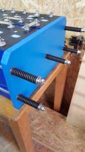
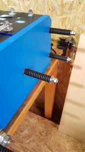
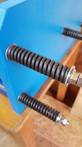
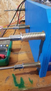
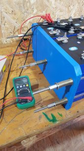
I’m just curious, I read through the whole thread and noticed everyone seems to be using the springs on the outside of the batteries over the rods and dealing with flex of the end plate, or building heavier to mitigate.
My my first question is why not make the fixture rigid with compression springs inside against the battery? For example, if it’s a 4 battery sandwich, it would be 5 batteries thick with a piece of plywood or metal against battery 4 and springs between that and the end of the fixture. Maybe something like a coil spring mattress if you will.
second question, I saw gas springs mentioned, but it seems creating a rigid fixture and using an air bag to a calculated pressure between battery and rigid fixture would also work. These air bags are commonly available for aftermarket suspension upgrades. while air is less permanant, it is also easy to adjust and work with. For that matter a small cluster of tennis balls between rigid fixture and batteries (using a rigid plate in between to protect batteries from localized forces) should yield the correct pressure.
In both examples forces are placed where they would directly resist battery expansion and not off to the edges relying on rigidity of fixture end pieces Which seems to me to stress out the edges of the batteries and not fully compress the centers where they would flex the most.
I’m enjoying the discussion you all have going and have seen some very nice prototypes of fixtures. Neat stuff.