diy solar

diy solar

Pack / Cell compression Optimized By Using Springs.

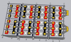
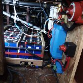
Probably not the right thread, but I didnt go with springs in the end. Because I have an arrangement with 3 parallel cells x 8S , I wanted to use fixed busbars across the 3 cells. I used 5mm neoprene between all cells. 1 bar (14psi) compresses almost exactly 1/2 the neoprene. So my 4 rows of 6 cells have 7 layers of 5 mm neoprene. I compress till the 35mm of neoprene is compressed to 1/2 (17mm total over the pack). Any swelling of cells will compress the neoprene but keep the cells in same relative position so no pressure on terminals, so I can use fixed busbars. I suspect longer term pressure on the neoprene will loosen as they permanently compress, but I can check torque on nuts too and adjust if needed. syspic.jpgpackplan.png
 
@PeterBC .... yes, the general cell compression thread would have been better for this.

We are trying to keep this one focused on the use of springs for compression.
 
OK, new thread for things other than springs providing compression.
 
Last edited:
OK I have read this thread about 3 times at this point I am just skimming trying to figure out what I have missed to calculate this properly. I thought I had the correct springs picked out but now I am sure I do not. I am building my new pack as a 3p 16s with the cells laid out in a 6 deep x 8 across cell pattern. I will have two rods on each end, and two rods between each set of 6 deep cells for a total of 18 rods. the compression fixture is 1/4" aluminum that is 61" long by 10.62" high formed in an L so that the bottom and one side are one piece and the backing (compression) plate is the second piece and moves. the backing plate is bent at 45° 3/8" up on the top and bottom for more rigidity and no flexing (these parts are on order and will arrive next week.)

total square inchs of the fixture is 648.6 square inches and I am shooting for the above mentioned 661 pounds across the face of one cell then with a surface are on the broad side of the cell being 76.32 square inches I would need 8.66 PSI to get the 661 pounds of force on the face of the cell. why do I get 8.6 psi when everybody is always talking 12psi? (different sized cell?) (CALB 200se plastic case.)

if that is the case that 8.6 psi is what I am shooting for, then it seems that with that being so I would need a total of 5616 pounds across the face of the fixture to compress the 8 across cell face, or 312 pounds of force per rod (18 rods). can anybody double check and see if/where i screwed the pooch on the math?

recap:

cells are 10.6" x 7.2 inch wide. compression fixture is 61" x 10.6" with 18 rods looking for that magical 661 lbs how do I calculate out the strength of springs needed? I was looking for a 3-4 inch spring for a 3/8" threaded rod if available to fit the location.
 

Attachments

  • compression pack.pdf
    431 KB · Views: 35
OK I have read this thread about 3 times at this point I am just skimming trying to figure out what I have missed to calculate this properly. I thought I had the correct springs picked out but now I am sure I do not. I am building my new pack as a 3p 16s with the cells laid out in a 6 deep x 8 across cell pattern. I will have two rods on each end, and two rods between each set of 6 deep cells for a total of 18 rods. the compression fixture is 1/4" aluminum that is 61" long by 10.62" high formed in an L so that the bottom and one side are one piece and the backing (compression) plate is the second piece and moves. the backing plate is bent at 45° 3/8" up on the top and bottom for more rigidity and no flexing (these parts are on order and will arrive next week.)

total square inchs of the fixture is 648.6 square inches and I am shooting for the above mentioned 661 pounds across the face of one cell then with a surface are on the broad side of the cell being 76.32 square inches I would need 8.66 PSI to get the 661 pounds of force on the face of the cell. why do I get 8.6 psi when everybody is always talking 12psi? (different sized cell?) (CALB 200se plastic case.)

if that is the case that 8.6 psi is what I am shooting for, then it seems that with that being so I would need a total of 5616 pounds across the face of the fixture to compress the 8 across cell face, or 312 pounds of force per rod (18 rods). can anybody double check and see if/where i screwed the pooch on the math?

recap:

cells are 10.6" x 7.2 inch wide. compression fixture is 61" x 10.6" with 18 rods looking for that magical 661 lbs how do I calculate out the strength of springs needed? I was looking for a 3-4 inch spring for a 3/8" threaded rod if available to fit the location.
You want the total square inches of the cells the fixture is acting on. Not the square inches of the fixture.
 
recap:

cells are 10.6" x 7.2 inch wide. compression fixture is 61" x 10.6" with 18 rods looking for that magical 661 lbs how do I calculate out the strength of springs needed? I was looking for a 3-4 inch spring for a 3/8" threaded rod if available to fit the location.
This is a detail that I dont think everyone agrees with but IMO, the springs on the ends are acting on only one row of cells. The springs in the middle are acting on 2 sets of cells. They should have twice the spring rate of the ones that are on the ends because they are acting on 2 sets of cells. You (IMO) should have 4 springs of a given spring rate and 14 that have 2x the spring rate of the 4.
 
You want the total square inches of the cells the fixture is acting on. Not the square inches of the fixture.
610 square inch on one face. do you mean both faces front and back, or just one side of the pack? if so, does that mean the rest of the way I am calculating is correct or incorrect?
 
Just one side. For you with 6 cells side by side the surface area you need to calculate off of is 10.6 x 7.2= 76.32 inches square for each cell.

total force required is 76.32"square x 12psi you have above is 915.84 lbs total "force".

915.84/4=228.96 for each of the 4 springs acting on a cell. This is what I was talking about in my last post though. The outside springs will be 228.96 but the inside springs will need to apply 2x as much force because they are acting on 2 cells. Some people just compress the spring twice as much. I used a spring with 2x the spring rate so I could compress the springs the same amount. There are pictures of what I did here: https://diysolarforum.com/threads/1997-isuzu-npr-build.17885/
sorry its 6 deep and 8 across, but the figures should still work. Thanks. those are the figures I got on the second try of calculating. I got different numbers each time depending upon how i calculated. the last couple of times I was just going off of the total sq" of the face of the compression fixture not just the combined cell faces.
 
Pics of the compression fixture.

I made the end plates from some 1/2", 9 ply Birch plywood from Home Depot. This is the experimental version, once I am convinced I have everything figured out I will rebuild it using 1/2" Baltic Birch plywood I have. The end plates are 12" high, because I didn't both to cut them to final size (the end plates were cut from a 12" x 24" piece of plywood).

View attachment 34379

There will be a bottom to the compression fixture, but the packs are going to be mounted on the rubber vibration isolators. Mounted to the bottom reinforcing tubes.

View attachment 34380

This pic shows the Belleville spring washers. I will cut the threaded rods to the correct length when I build the individual 4 cell packs.

View attachment 34381


This is what I have in mind for the final packs. I am using 1"x1" square tubing instead of Unistrut. The bus bars are braided copper straps. Each pack of 4 cells are individual so I can more easily remove them from my van. I live in Phoenix AZ and want to be able to move the cells to the air conditioned house when I am not using the van as an RV in the summer. The cable joining the two packs in series is a longer piece of 1/0 AWG wire. I wanted to give this piece of cable as much flexibility as possible, hence the reason why it is the longest.

View attachment 34382
Do you have a link to the springs you used?
 
In general, to determine the spring capacity needed. .... I am using Sq In since the 12 psi number is what we have to work with .... but the same principle will work if converted to metric.

1. Determine the area of the side of the cell.
So, for a cell that is 7" x 8", the area will be 56 Sq Inches.
2. Multiply the area by 12 since we want 12 psi. (56 x 12 = 672 total lbs of force needed)
3. Divide the total force needed by the number of springs being used. (672 / 4 = 168 lbs per spring if 4 springs are being used.)

There are pictures of a pack done by Dacian (Electrodaucus Guy) on that other thread ... maybe it can later be added here along with pics from others who have done this.
Does this apply when springs are used on both sides? (ie does the same calculation apply whether the other side is a "wall" or a similar set of springs?)
edit: if I understand correctly the above stays the same and the number of springs is increased, so effectively divide the force by 2 and use cheaper springs.
 
Last edited:
Does this apply when springs are used on both sides? (ie does the same calculation apply whether the other side is a "wall" or a similar set of springs?)

No, the "wall" provides equal and opposite force to the springs, so you don't gain anything by having springs on both ends.

There's an old physics problem where you have two people pulling on both ends of a rope, versus tying one end of the rope to a wall and having both people pull on the other end. Which situation puts more tension on the rope? The answer is that having two people pull on one end gives double the tension, because the wall provides an equal and opposite force to the other end.

It's the same with your springs. So if you want to use half-size springs, you need to double the number of rods.
That seems to make sense, thank you :) I take it there isn't much of a benefit to having springs on both sides then?
 
That seems to make sense, thank you :) I take it there isn't much of a benefit to having springs on both sides then?

The only benefit would be if for some reason you needed the pack to be able to expand in both directions.
 
Does this apply when springs are used on both sides? (ie does the same calculation apply whether the other side is a "wall" or a similar set of springs?)
edit: if I understand correctly the above stays the same and the number of springs is increased, so effectively divide the force by 2 and use cheaper springs.
What @Oberon said.
 
I am hoping someone could double check my logic.

My build will consist of two compression packs with 4 cells each with 3/4 inch ply each side and springs (4 each) only on 1 side of each compression build. Both builds will be next to each other each having their own springs and their own 3/4 inch piece of plywood compression.

I was thinking that instead of making them both completely separate I could have them share a backing plate (3/4 ply) on the opposite side of the springs. Ultimately I'd like to build an enclosure everything connected except for the sides with the springs that would be free to compress or decompress as needed.

Would having the two 4 cell compression builds share a backing plate opposite side the springs mess up the compression? Would it double the force pushed back?
 
Last edited:
I am hoping someone could double check my logic.

My build will consist of two compression packs with 4 cells each with 3/4 inch ply each side and springs (4 each) only on 1 side of each compression build. Both builds will be next to each other each having their own springs and their own 3/4 inch piece of plywood compression.

I was thinking that instead of making them both completely separate I could have them share a backing plate (3/4 ply) on the opposite side of the springs. Ultimately I'd like to build an enclosure everything connected except for the sides with the springs that would be free to compress or decompress as needed.

Would having the two 4 cell compression builds share a backing plate opposite side the springs mess up the compression?
Nope, will have no effect. as long as each pack has 4 springs they can all be the same and you are good. The only concern I would have is if you pick up one end, the group of cells on the other end might see some goofy loads but I doubt it would be of any consequence.
 
Nope, will have no effect. as long as each pack has 4 springs they can all be the same and you are good. The only concern I would have is if you pick up one end, the group of cells on the other end might see some goofy loads but I doubt it would be of any consequence.
Great. Good to know. I was concerned it might double the force pushed back to distribute the force pushed back weird if the cell expand at different rates.
 
Great. Good to know. I was concerned it might double the force pushed back to distribute the force pushed back weird if the cell expand at different rates.
If each pack has independent plates on either end, you will get expansion/contraction on both ends even if the springs are only one end (so the center cell or two will be stationary with a small amount of expansion / contraction on either end of the pack).

With a common plate on one end, both packs will be forced to expand/contract by the same amount on that one end.

That’s probably going to be the case anyway and should be fine, but in the extreme case that one pack expands/contracts much more than the other (including the initial phase while the cells are settling over the first few cycles), the common plate will force the far plate and all the cells in between to move more than it would if it had an independent plate on both ends.

Again, should be fine, but what are you really gaining by having a single double-width plates versus two singles? (Cost, number of springs, etc… is all the same, right?).
 
Back
Top