I need some advice.
For the past year, I've had 4 batteries in my camper. I built the batteries from 130 Ah CALB cells I pulled from an EV I built several years ago. I have a 100 Ah or 120 Ah Overkill BMS in each battery. The batteries are connected to the buss bars with Anderson plugs to make connection easy. For the strictly DC system, that all worked just fine. With the exception of the BMS disconnecting when any of the cells reaching 3.6 V which takes the battery out of the mix... guess that's the problem with a common port BMS.
I chose the 100 Ah BMS thinking that eventually I'd add an inverter which would draw a max of 200 Amps at a nominal 12 VDC from the battery bank. In parallel, each battery should have no trouble providing 25% of that 200 Amp load. Well, 'eventually' is here and this winter's project is to upgrade my camper with a Victron Multiplus-II 2x 120v inverter. BUT at a recent Victron training event, I learned about ripple voltage/current caused by the inverter when cables are too long, or resistance is too great between the inverter and the battery bank. Now, it is all about reducing resistance between the batteries and the inverter, so those Anderson plugs have to go. Oh, and I also have a 150 Amp thermal breaker between each battery and the buss bar as overcurrent protection.
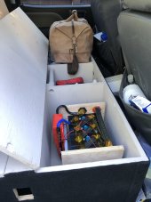
Without the Anderson plugs, I want to move to battery terminals installed on the side of each battery box. I've searched this forum for discussions describing how others have boxed their batteries. I went with simple plywood boxes that work just great to protect the batteries. I have the BMS attached to the side of the battery, within the minimally vented box.
1. I plan to add battery terminal posts to each box and use 0 AWG cables between each battery and the buss bars, to eliminate the Anderson plugs.
2. Which overcurrent device has less resistance? A 150 Amp fuse, or a 150 Amp thermal breaker? I could add the fuse to the inside of the box for a cleaner installation. Or keep the thermal breaker in the circuit, but outside of each box.
3. Anyone see a fatal flaw in my intentions for this modification?
Thanks in advance for your thoughts!
For the past year, I've had 4 batteries in my camper. I built the batteries from 130 Ah CALB cells I pulled from an EV I built several years ago. I have a 100 Ah or 120 Ah Overkill BMS in each battery. The batteries are connected to the buss bars with Anderson plugs to make connection easy. For the strictly DC system, that all worked just fine. With the exception of the BMS disconnecting when any of the cells reaching 3.6 V which takes the battery out of the mix... guess that's the problem with a common port BMS.
I chose the 100 Ah BMS thinking that eventually I'd add an inverter which would draw a max of 200 Amps at a nominal 12 VDC from the battery bank. In parallel, each battery should have no trouble providing 25% of that 200 Amp load. Well, 'eventually' is here and this winter's project is to upgrade my camper with a Victron Multiplus-II 2x 120v inverter. BUT at a recent Victron training event, I learned about ripple voltage/current caused by the inverter when cables are too long, or resistance is too great between the inverter and the battery bank. Now, it is all about reducing resistance between the batteries and the inverter, so those Anderson plugs have to go. Oh, and I also have a 150 Amp thermal breaker between each battery and the buss bar as overcurrent protection.
Without the Anderson plugs, I want to move to battery terminals installed on the side of each battery box. I've searched this forum for discussions describing how others have boxed their batteries. I went with simple plywood boxes that work just great to protect the batteries. I have the BMS attached to the side of the battery, within the minimally vented box.
1. I plan to add battery terminal posts to each box and use 0 AWG cables between each battery and the buss bars, to eliminate the Anderson plugs.
2. Which overcurrent device has less resistance? A 150 Amp fuse, or a 150 Amp thermal breaker? I could add the fuse to the inside of the box for a cleaner installation. Or keep the thermal breaker in the circuit, but outside of each box.
3. Anyone see a fatal flaw in my intentions for this modification?
Thanks in advance for your thoughts!

") Soon as I know I have a workable design, I'll order the remaining quantity.
Soon as I know I have a workable design, I'll order the remaining quantity.