SoundinSpirit
New Member
Since I've been searching this group for awhile about this topic and not finding any others trying this, I had to do it...
Thanks @Will Prowse for sharing that video of the dual Daly 60 amp bms modules in parallel!
Dual Overkill 120 amp BMS running in parallel WORKS GREAT- though per Steve at Overkill, it is not recommended.
I have new 4s 280 amp hour cells, grade A...Top Balanced in bulk with AGM battery charger, then topped off with a Hobby LiFe charger. My plan is to get 4 more cells, but I wanted to plan for that time about 2 months from now for shipping. I also have a 2000 watt inverter I wanted to run, which should draw about 180 amps under my planned, short duration, max load.
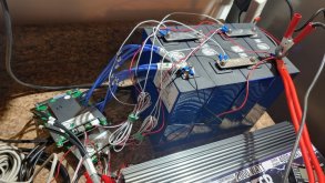
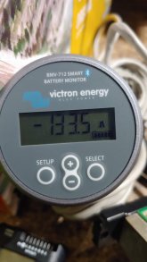
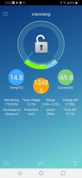
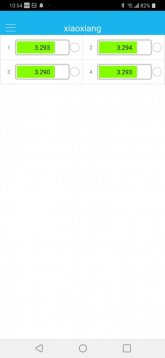
Wiring the BMS modules using a Victron BMV-712 and a hobby load tester, I was able to see the 60 and then 135 amp draw split between the two modules. It is not a perfect 50/50 split, but really close... The BMV was showing the load split and the BMS reflected this as well! Both BMS modules show the same cell voltage. Charging using a AGM charger at about 20 amps is working fine too.
Does it work? YES! There seems to be zero issue in doing this too while bench testing.
My WHY is explained above... The how is here too. I am actually using TWO AGM battery chargers as well. I DID want the reliability, local prep with wires, etc of Overkill. Also the Stateside shipping speed.
While I didn't read about it on the internet, I did watch Will's video using two 60 amp Daly BMS in parallel...
I thought this through and checked everything step by step very cautiously...
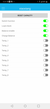
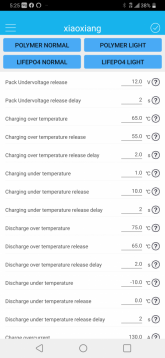
NOT doing it on the cheap either... the two Overkill BMS were about $250 with lugs crimped, etc. While I DO feel comfortable using this setup longer term, I will be getting four more cells and splitting up the BMS. Once again, in emailing Steve at Overkill, he did say he recommends against this usage, but if it works...it works, right? I WILL be monitoring cell voltage from the app and multimeter more cautiously as this is in use.
For the next few camping trips, I will be good to go until the next four cells roll in...
Pretty stoked!
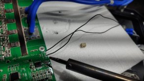
Initially, I did encounter an issue with one BMS. But it's unrelated to using in parallel. I swapped the temp probe and the issue stayed with the board... so? The BMS works fine until it hits high voltage/low voltage/overcurrent shutdown. Then it gets locked out of self-reset with discharge turned off. Working it out with Overkill, but probably a faulty module... The other one works perfectly.
In response to a couple questions I had...
Cell voltage on both BMS matches and pack voltage matches too. When testing with two different multimeters on cell terminals, individual voltage is off by about .10 volt. BMS measures higher... Multimeter pack voltage is also off from BMS, but matches the BMV-712 exactly. This variance is noticed with either bms from multimeter and whether they are in parallel or singularly wired.
Hope this helps for anyone wondering the same as I did... Please ignore the wire mess too. I'll have it all cleaned up and dialed in as I get the cells in a box! I think I may also make a stud for the main positive and Neg. Putting two lugs on there and balance leads seems too little thread engagement ...
Thanks @Will Prowse for sharing that video of the dual Daly 60 amp bms modules in parallel!
Dual Overkill 120 amp BMS running in parallel WORKS GREAT- though per Steve at Overkill, it is not recommended.
I have new 4s 280 amp hour cells, grade A...Top Balanced in bulk with AGM battery charger, then topped off with a Hobby LiFe charger. My plan is to get 4 more cells, but I wanted to plan for that time about 2 months from now for shipping. I also have a 2000 watt inverter I wanted to run, which should draw about 180 amps under my planned, short duration, max load.
Wiring the BMS modules using a Victron BMV-712 and a hobby load tester, I was able to see the 60 and then 135 amp draw split between the two modules. It is not a perfect 50/50 split, but really close... The BMV was showing the load split and the BMS reflected this as well! Both BMS modules show the same cell voltage. Charging using a AGM charger at about 20 amps is working fine too.
Does it work? YES! There seems to be zero issue in doing this too while bench testing.
My WHY is explained above... The how is here too. I am actually using TWO AGM battery chargers as well. I DID want the reliability, local prep with wires, etc of Overkill. Also the Stateside shipping speed.
While I didn't read about it on the internet, I did watch Will's video using two 60 amp Daly BMS in parallel...
I thought this through and checked everything step by step very cautiously...
NOT doing it on the cheap either... the two Overkill BMS were about $250 with lugs crimped, etc. While I DO feel comfortable using this setup longer term, I will be getting four more cells and splitting up the BMS. Once again, in emailing Steve at Overkill, he did say he recommends against this usage, but if it works...it works, right? I WILL be monitoring cell voltage from the app and multimeter more cautiously as this is in use.
For the next few camping trips, I will be good to go until the next four cells roll in...
Pretty stoked!
Initially, I did encounter an issue with one BMS. But it's unrelated to using in parallel. I swapped the temp probe and the issue stayed with the board... so? The BMS works fine until it hits high voltage/low voltage/overcurrent shutdown. Then it gets locked out of self-reset with discharge turned off. Working it out with Overkill, but probably a faulty module... The other one works perfectly.
In response to a couple questions I had...
Cell voltage on both BMS matches and pack voltage matches too. When testing with two different multimeters on cell terminals, individual voltage is off by about .10 volt. BMS measures higher... Multimeter pack voltage is also off from BMS, but matches the BMV-712 exactly. This variance is noticed with either bms from multimeter and whether they are in parallel or singularly wired.
Hope this helps for anyone wondering the same as I did... Please ignore the wire mess too. I'll have it all cleaned up and dialed in as I get the cells in a box! I think I may also make a stud for the main positive and Neg. Putting two lugs on there and balance leads seems too little thread engagement ...