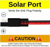
I am considering expanding the solar power available to my trailer by adding a side port to attach a portable solar panel. The portable panel, when plugged in, would be wired in parallel with the fixed panel that is mounted on the roof. I have a concern about how to wire the panels, MPPT charge controllers and battery.
I've seen videos where someone simply hard-wired the side-plug in parallel with the wires coming from the fixed PV panel on the roof. This seems like a bad idea for at least two reasons:
1. If the portable panel happens to be wired in reverse, this will loop the negative and positive outputs of the two panels. All the current from one would flow through the other. At best, the charge controller isn't getting any energy. At worst, something is going to get damaged and/or melt.
2. If one panel is shaded or is otherwise generating a lower voltage than the other, then the more highly energized panel is going to drive current through the other panel instead of the charge controller. This again results in less power flowing to the charge controller, but is also going to heat up the other panel, which further reduces it efficiency.
One obvious way to fix this problem is to put in blocking diodes to prevent current from flowing into the panels. This assumes that the solar panel junction boxes do not include blocking diodes (difficult to tell from the specs as no one seems to discuss specifics of the junction boxes, but it seems that they only have bypass diodes to handle shading on the panel itself). While this is inexpensive and would work, the diodes incur about a 0.5V drop, which represents about a 5% loss of power not to mention a higher threshold for being able to drive the charge controller.
The other approach is to wire each panel to its own (lower amperage) charge controller, and then wire the battery side of both controllers in parallel to the battery. This is obviously more expensive, but would seem to be the best solution in terms of isolating the panels from each other with minimal energy loss to address all the issues associated with mismatched voltage outputs and reversed polarity (which I guess is an extreme case of "mismatched" voltages).
Actually, I guess there is one more possible solution. Wire the panels in series with a bypass and diode around the portable. Handles shading on the portal panel as well as outright removal. Only question then is how to handle reversed polarity on the portal panel.
Has anyone else tried to design a system where they had to address this sort of issue? Any thoughts on what approaches work best?
Last edited:


