diy solar

diy solar

Parallel Supercapacitors with LFP bank

8_Hz_WAN_IP

New Member
Joined
Aug 11, 2020
Messages
29
I'm a newbie, but I have a semi-advanced question that might inspire a more educated/technical discussion here in the advanced area.

For the past few years, I've assumed that connecting supercaps in parallel to your LFP bank (or any other chemistry) will increase power availability by relieving battery stress during overload conditions, leading to a higher lifecycle count. All this while maintaining high overall system efficiency.

I was wondering if a bank of cheap supercaps (totalling bank voltage) in parallel with an LFP off grid bank has worked for any of your solar applications as far as producing better discharge conditions and lifecycle count increases?
 
there is no cheap supercap.
if you have " battery stress during overload conditions," you design is bad and must be corrected.
correcting an error by doing another error is a common human behavior.

you just need to increase battery capacity to avoid overload conditions
or reduce load.
 
A capacitor's internal resistance would be in parallel with the battery's internal resistance. The capacitor's internal resistance would need to be low compared to the battery in order for the capacitor to deliver the majority of the current in a high demand surge. Those type of capacitors are of the type made for high powered pulse laser discharge, rail guns, magnetizing fixtures, and similar uses. Other types of super capacitors have somewhat higher internal resistance and can supply power at a low amp delivery rate better than a high amp rate. So pay close attention to the internal resistance when planning such a build.
 
Cheaper to just build a bigger battery. In cars this my make sense because of weight and huge load variation on accel and de-accel, along with regen braking. You can easily have a plus and minus instantaneous load change of almost up to 100kw in a car/truck.

When super cap prices come down it may help on cloudy days and like well pump startup. Adding caps is like buying a bigger inverter so adding caps to an existing inverter my get you through a problem or for a new install just buy the bigger inverter to begin with.

Great discussion though.
 
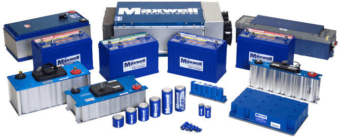
I have just ordered a system that includes a Maxwell supercap in parallel with a LiFePO4 pack.

This type of setup is widespread in Australia, scope trace shows elimination of AC ripple during AC coupled charging, as well as reduced peak current from LiFePO4 pack.

This is a sensible design in my view, i will document it on this forum when i get to putting it all together.
 
Adding caps is like buying a bigger inverter so adding caps to an existing inverter my get you through a problem or for a new install just buy the bigger inverter to begin with.

No. Adding supercaps reduces the peak current load on your battery, it won’t help at all with the ability of your inverter to handle high surge current on the AC side.
 
No. Adding supercaps reduces the peak current load on your battery, it won’t help at all with the ability of your inverter to handle high surge current on the AC side.
I kind of disagree. If the battery pack is not big enough and a large draw hits, the unit will shut down. If you have a larger inverter with larger capacitors inside it, they are charged at power on and store power that will get you through a large power draw. So I believe a larger inverter will get you through a large instantaneous power draw like a motor starting with the same size battery.

I have just ordered a system that includes a Maxwell supercap in parallel with a LiFePO4 pack.

This type of setup is widespread in Australia, scope trace shows elimination of AC ripple during AC coupled charging, as well as reduced peak current from LiFePO4 pack.

This is a sensible design in my view, i will document it on this forum when i get to putting it all together.
Same situation as above. If you are having issues with the inverter you currently have adding super caps will likely help, but buying a bigger battery will be the cheaper option.

Or with a new system a bigger inverter will have the caps already in it and be able to perform better.

How big are the caps you ordered and what was the cost of them?

Again great conversation. I am not an expert but do have a scope and have not seen any ripples on my AC waveform. Guessing every inverter and installation is different. I run a constant load just over 500 watts and run a 4 kw inverter. Battery is 17 cells 280 Ah (3.5 volts *17 cells = 59.5 VCD) or 16.66 kwh... We are all learning.
 
Last edited:
Sorry about the length, but this is on topic here. I have been messing around with an idea for a Hybrid electric car.

As much as I like the idea of a full electric, the weight of a battery pack for 500 mile range becomes a big problem. Gasoline hold so much more energy per pound, it is very hard to get past that fact. But most hybrid cars are built backwards, and I think the issue is surge current. I current have a Ford C-Max hybrid, not a plug in. The battery is very small at just 1.4 KwH. Most of the driving power is coming directly from the gasoline engine. The battery can keep the car rolling at speeds up to 75 mph with the engine off, but for only about 3 miles. The regen braking can totally top out the battery down a moderate hill, and sadly, it can't supply a lot of braking force due to the current limitation of the tiny battery bank. But with the electric help, it does get me well over 40 mpg and a 500+ mile range.

So what if we upped the battery size to just 5 to 10 KwH's, but cut the gasoline engine down to a puny 600 cc or so, that could run a very efficient alternator that makes enough power for pulling the car up a grade. Say maybe 35-50 hp is all it takes. When the battery goes below 50%, the engine runs at peak efficiency, until the battery is at 80%. The battery could run a motor directly and have a short term power of 150 hp for acceleration, but that puts a lot of stress on the battery, and it would cycle constantly. And under braking, the regen would be weak, and it would need to use friction brake pads for anything past light stopping. A small engine tuned for a narrow operating rpm can be very efficient. Maybe even a turbine?? It does not need to change speed with the tires so it can be optimized with the generator design. Maybe even a fuel cell?

Now enter the ultra capacitor bank.
It can't be directly paralleled with the batteries. If you pulled a very high current surge, it would pull the capacitor voltage down a bit as that is the only way a capacitor gives out energy. But now the battery bank is held down to that voltage as well, and the current from the battery goes crazy high trying to bring the capacitor back up to the previous battery voltage. A small resistance to the battery would save them from destruction, but would throw away a lot of energy into heat. This will likely just fail after a short time. So my design uses a main battery that is at a higher voltage than the capacitor bank. There is a buck/boost converter that can smoothly take energy from the battery and push it as needed at a controller rate to the ultra capacitor bank, or it can pull it from the capacitor bank and push it back to the batteries. The motor controller then has it's own semi normal high capacity electrolytic capacitor bank feeding the MOS FET bridge to the motor windings. And there is another buck/boost converter between the motor controller capacitors and the ultra capacitor bank. The dual voltage converters will add a little more loss, but with modern electronics, they can be better than 97% efficient each. I feel the benefit is worth it

So the car is charged (plug in?), the main battery is at 80% (have to leave some room for braking, or going down a hill). The ultra capacitor bank is charged to 3/4 of it's max voltage, same reason here. Mash the accelerator, and the motor controller starts sucking AMPS!! The ultra capacitor starts to discharge, but the second converter is able to keep boosting the voltage to the motor controller to keep the acceleration going long enough to get the car to 100 mph or so. The first converter will start pulling power from the battery bank and try to help keep the ultra capacitors charged. When you let off the accelerator, it has to still keep pulling battery power to get the ultra caps back to the 75% resting voltage. If the main battery starts getting low, it will fire up the generator engine to help out.

Now you slam on the brakes. The motor now becomes a generator, and the motor controller can stuff huge current into the ultra caps to quickly slow the car. As their voltage climbs, the first converter will start pulling power and stuffing it back into the batteries at a rate they can handle. If the ultra caps do get too high in voltage, it will then finally need to use the friction brakes, but it will be at a much higher stopping force than a battery only EV or Hybrid.

If this get's balanced properly, the battery can be 1/10 that of a Tesla, and still get ludicrous acceleration and braking, and a tiny lightweight 10 gallon gas tank could give 600 miles of range. The engine is only turning a generator so it can be located anywhere for balance. The battery is small and light and could fit just under the seats so you don't have the fat floor like a Tesla or Bolt etc. The Ultra cap guys say Lithium bats are for Kilowatt Hours, the Ultra Caps are for Megawatt Seconds. 500 HP is just 375,000 watts (1/3rd of a megawatt), and if we have it for just 6 seconds, (only used 625 watt hours) we can be over 100 mph. You just might have to wait for a minute to do it again, or slam the brakes and get much of it back quickly.

I see this as the future of cars. Full electric cars just need too much battery, and charging is so much slower than filling a gas tank. And the weight of a 500 mile range battery makes a car handle like a moving van. Even if it can launch to 60 in 2.5 second, it still can't turn and stop like a performance car should. Cars are just too heavy now. I thought my little C-Max was a pig at 3,600 pounds. A Tesla X is close to 6,000 pounds.
 
first you need to take in account that supercap are able to release energy fast, but the reverse (storing it) shoud not be true.
so you have to check how fast you can recharge a supercap, and if the electronic required is not killing the project.
Then , you need to take in account that all the elements of the car have been optimized to work together.
Modifiying one, could require to change another, then another....
if your project if full of "If" so you could work to get the real data instead assumption.
 
The modern Ultra Capacitors are equally capable of super fast charge and discharge. But even at their current state, a bank large enough to give the 375,000 watts for 10 seconds is quite large. Check out this page
They have a module now that is rated for 1900 amps of charge or discharge peak current at up to 125 volts. This means it can put out 190,000 watts, but not for long enough. It has just 144 watt hours, but it only weighs 63 Kg. To meet my design, it would take 4 or 5 of these.

A typical efficient car only takes about 12 hp to stay moving at 60 mph (100 kph) but to be able to climb a long hill, the combustion engine does need more than double that. I have to drive over the Tejon pass from time to time. That is a 3,500 foot climb, and it does get fairly steep in a few places. The engine needs to make enough power to pull up it. Yes, we can also pull some battery, as we get to suck most of the power back on the way down the other side. In my C-Max, I do my best to discharge the battery as much as possible going across the summit, but I still end up with the tiny 1.4 KWH battery completely topped out well before the bottom, so I have to use friction braking to keep from speeding on the down grade. For this reason, I figure we need at least 4 times the battery, but that is still tiny compared to a traditional battery only electric car. Having the ultra cap suck up the power, also allows the main battery to be charged at a much slower and steady rate. That will greatly extend the battery life.

This is not theoretical. It is just that it has not been cost effective to lump all this into a single car at a price anyone can buy just yet. And YES, Tesla bought Maxwell for their super cap technology. But I doubt they will ever use the fuel burning charger that I want for far more range at less weight.
 
and have not seen any ripples on my AC waveform.

The AC ripple is on the DC bus when charging with an AC coupled system. Some studies have shown this ripple is detrimental to battery life.

I misunderstood your comment about inverter size, i thought you meant installing a supercap would increase the surge capacity of a small inverter- not that installing a larger inverter would lower the surge current from the battery.

I will attempt to update this thread with scope traces when my pack is operational.
 
so I have to use friction braking to keep from speeding on the down grade. For this reason, I figure we need at least 4 times the battery, but that is still tiny compared to a traditional battery only electric car. Having the ultra cap suck up the power, also allows the main battery to be charged at a much slower and steady rate. That will greatly extend the battery life.

The Maxwell supercaps i am using are second hand units out of trains, and are used for just that purpose.
 
The AC ripple is on the DC bus when charging with an AC coupled system. Some studies have shown this ripple is detrimental to battery life.
I will have to check the DC side and see. Can the normal guy use a multi meter set on AC to see how much AC is riding on the DC to the battery?

:)
 
Decent quality inverters have input filters to reduce the 60/120 Hz (or 50/100) ripple that gets pulled on the batteries. That is why most inverters male a healthy spark when you hook it up due to the large (for electrolytic caps anyways) capacitors. A good power factor corrected inverter/charger will have the input current vary with the AC voltage waveform, so some ripple is going to be there. It would take very large inductors as well as caps to fully remove it. My Shcneider is charging now, and the AC ripple current at the battery is at the resolution limit of my meter. By wrapping the cable through twice, I got .01 amps of AC ripple with 30 amps of DC charge current. When it is inverting later, I will try it again.
 
I just may be adding a capacitor bank to my battery bank.

Using an AC clamp amp meter, I was a bit shocked to see 23 amps of current ripple on the main battery cables. And this is running just 30 amps DC at 57.2 volts. Just some large electrolytic caps at the battery, on the far end of the 8 foot DC cables, may be able to take some of that off the batteries. Too bad it is a relatively low frequency, as it is following the AC output waveform. A choke coil would have to be huge.

As for voltage, I wanted to check my cell impedance anyways... I have easy access to the terminals of the 4S section of cells. Since this is 1/2 of the current path, it is seeing just 11 amps of ripple on the amp clamp. My Fluke true RMS meter shows just 18 millivolts of AC on the buss bars across 4 cells. If the clamp meter is also close to a proper RMS reading, that would mean an internal resistance of 0.0016 ohms for 4 series cell groups, or just 0.0004 ohms, less than 1/2 milliohm for each cell group. It will take a lot of capacitor to cut that ripple much.
 
Last edited:
A capacitor can only deliver power by decreasing in voltage. Energy = 1/2 C V^2 if I remember correctly.
If voltage dips much, the (paralleled) battery will supply massive current. You can't access much power from the cap, and when you do you cycle the battery.
Would be better to put the supercap on its own inverter (with very low cut-off voltage)
Or, put the caps on the PV side of an MPPT charge controller. With battery at full voltage, it stops drawing power. When battery voltage dips due to a load, MPPT draws as much as it can from supercap attempting to maintain float voltage.
 
I'm a newbie, but I have a semi-advanced question that might inspire a more educated/technical discussion here in the advanced area.

For the past few years, I've assumed that connecting supercaps in parallel to your LFP bank (or any other chemistry) will increase power availability by relieving battery stress during overload conditions, leading to a higher lifecycle count. All this while maintaining high overall system efficiency.

I was wondering if a bank of cheap supercaps (totalling bank voltage) in parallel with an LFP off grid bank has worked for any of your solar applications as far as producing better discharge conditions and lifecycle count increases?
I have installed a supercapicator bank parallel with two other LFP 280ah battery bank. It's been installed for the past two months now and it does help on the initial current draw, when it rains heavily enough my sump pump starts every minute and run for about 20 second. I can see a 6 amps draw (at the start of the pump) on the capacitors and goes down very fast.
The battery bank current draw is just seconds away at 2,3,4 amps and up. As the capacitors only provides a current draw at the start. This is only an observation I had with the sump pump, which is 120v 8 amp.
Now just think about it when the well pump goes on ~1600 watts, or my pool heat pump at 2900 watts,.
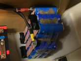
Hope this helps, these are cheap aliexpress capacitor, 2.7v 3000f. I have 22 of them in serries.
 

Attachments

  • 48D10824-CC31-4552-AE0E-458432C432A8.png
    48D10824-CC31-4552-AE0E-458432C432A8.png
    569.8 KB · Views: 31
when it rains heavily enough my sump pump starts every minute and run for about 20 second.

Sounds like sloshing of the water turns the switch off again.
It ought to be one with more hysteresis that run longer. Or maybe the sump is so small it only takes seconds to empty?

"2.7v 3000f. I have 22 of them in serries"

I can't quite make out if the photo actually shows them all in series or not. Where the cables attach, it appears to have copper sheet going to two capacitors, not one.

With 22 in series, that would be 22 x 2.7 = 59.4V, 3000/22 = 13.6 F

energy (Joules or W seconds) = 1/2 C V^2 = 0.5 x 13.6 x 54^2 = 19,800 at 54V charge
0.5 x 13.6 x 42^2 = 12,000 at 42V charge
19,800 - 12,000 = 7,800 Joules released as voltage pulled down from 54V to 42V.
That's 7.8 kW for one second, a nice kick to turn over a motor even if battery capacity is approximately zero Ah.

What sort of Capacitor Management System do you use?
With capacitors in series, any leakage within or across some of them would cause the others to bear the brunt of total applied voltage.
Any difference in capacitance would divide voltage unevenly.
You ought to have something like a k-ohm resistor across each capacitor to equalize voltage. 22 kohm at 54V is 2.5 mA drain. t = RC = 1000 x 3000 = 3e6 seconds or 35 days. Quite along time constant, but should help keep them balanced.

Or, a zener and series resistor across each capacitor. That would have lower current draw below knee voltage, but would draw much more current to perform balancing above the knee.
Yes sump is small, I prefer to have the water evacuated before it becomes even with the weeping tile.

These are all 16 v 500 farad banks with balancing circuit on each two capacitors,
I used 4 bank minus 2 capacitor, hook up in serries to give me 59.4 v.
My batteries top voltage is 56.8 v so I needed at least 21 capacitor for that voltage.
But because the balance circuit is good for two, I've put 22.
The capacitance is 3000/22 = 136.3636 farad
 
Last edited:
Back
Top