Samsonite801
Solar Wizard
- Joined
- Oct 15, 2020
- Messages
- 2,988
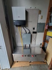
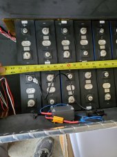
I finally got around to putting together my 12v and 48v battery banks (holder/clamp assemblies)...
Just thought to post some pictures of it as a couple people had asked me before here.
Still have to mount the BMS's, install the heat pads on bottom plate, thermostats, wiring, etc...
But it's nice to get this far for today. Simple design, I basically did similar to a few others here had done...
I had the 6061-T651 aluminum plates all pre-cut out by cut2sizemetals.com
Used my drill press and c-clamped all the end plates together and drilled all the holes out at once using top one as template.
Took 2 evenings after work, not too hard so far.
Last edited: