diy solar

diy solar

Plan for 50A 5th wheel install

BretS

New Member
Joined
Mar 30, 2021
Messages
171
Copying this over here from beginners corner...

Drew up a rough plan for phase I of my 50A 5th wheel install. Using a MultiPlus 12/3000/120-50 2x120V Inverter/Charger, 930Ah DIY bank, REC active BMS/precharger, Orion DC-DC charger. Once that is in and working, and my bank account can handle it, phase II will be nine 210W panels and 3 Victron MPPT SCCs. The battery bank is split with a 4/0 AWG connecting them to make install a little easier and more flexible (fitting them under my steps in an open spot). Not every detail is covered, but do you see any major flaws in my plan? I realize the wire size will be large.

One question I have - I have been told SCCs cannot be switched off of the batteries. But isn't the purpose of the BMS to protect the battery by disconnecting it? So would you connect the SCCs on the battery side of the BMS contactor? My thinking was that you would set the SCCs to charge at parameters within the parameters of the BMS - that way, the SCCs would be off if the parameters of the BMS disconnected the battery at the contactor. Am I missing something there??System plan 1.jpg
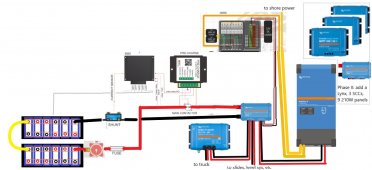
 
Be sure to keep that yellow cable as short as possible. There's an unacceptable level of inductance if it's too long. 15cm max is the rule to follow.
 
Second up, if you're using victron SCC, you can just use the enable port and turn them on and off.
SCC disconnect behavior varies by manufacturer...
 
Be sure to keep that yellow cable as short as possible. There's an unacceptable level of inductance if it's too long. 15cm max is the rule to follow.
That's only 6 inches... going to be tough to get it that short. I don't understand why it is different than the other cables - is it because it is mid bank?
 
I put my on off switch after the fuse.

THose Blue Sea on add switches are rated for a lot of amps. The version I got, the contacts to attach the cables to were pretty close to the backing, like a 1/4” close.

Also, if you’re ditching the generator altogether, I think having an option to charge off the truck is decent.

What is the box labeled to levelers and slide outs? I thought it was a 24 volt to 12 volt DC to DC converter, but don’t think so.
 
You will need to sort out how you setup a discharge-disable for your load center and the other 12V loads. Usually a Battery Protect works well for this, but you can also hookup another contactor to the REC.

The load center, slides, levelers, etc, should all be off that discharge ok circuit, so ideally you have one Lynx output dedicated to that.

For charge enable you plan to use canbus off the REC?

You don't need a Lynx for the 3 SCC -- you can combine them onto a small busbar or post and then into the original Lynx.
 
I put my on off switch after the fuse.

THose Blue Sea on add switches are rated for a lot of amps. The version I got, the contacts to attach the cables to were pretty close to the backing, like a 1/4” close.

Also, if you’re ditching the generator altogether, I think having an option to charge off the truck is decent.

What is the box labeled to levelers and slide outs? I thought it was a 24 volt to 12 volt DC to DC converter, but don’t think so.

I had the switch there, but someone suggested putting it first in case the fuse needed changed - it would make it easier. I can put it back if need be.

My generator is in the back of my truck and if I use it, it is with the shore power cord and 50/30 adapter. I wanted the truck charge for long drive days - especially until I get all of the solar installed.

The lines to the levelers and slide outs is coming from the Lynx distribution box. I need to sort out the factory wiring and probably put a couple of junction bus bars to hook them up. The DC-DC converter is the one to the truck.
 
what do you mean turn SCC off... there isn't a real need for that?

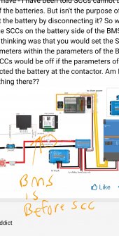
also your BMS is before the SCCScreenshot_20210501-202900_Chrome.jpg
 
Fuse should always be the first device after the batteries. It can be changed by turning off the 2nd device, the mechanical shutoff so the battery and fuse is now isolated and swap fuse, then turn mechanical disconnect back on.
 
You will need to sort out how you setup a discharge-disable for your load center and the other 12V loads. Usually a Battery Protect works well for this, but you can also hookup another contactor to the REC.

The load center, slides, levelers, etc, should all be off that discharge ok circuit, so ideally you have one Lynx output dedicated to that.

For charge enable you plan to use canbus off the REC?

You don't need a Lynx for the 3 SCC -- you can combine them onto a small busbar or post and then into the original Lynx.

If the REC contactor is cutting power to the Lynx, do I need another contactor? I thought that would disable all discharging.

I do have the slides and levelers off of one Lynx output, and the load center 12V loads off of another Lynx output. I'm not following you .

I haven't totally figured out what to do using canbus. I didn't want a screen, only bluetooth to my laptop. I'm still working on that.

I thought I needed another one because all 4 outputs of the current Lynx are taken.
 
what do you mean turn SCC off... there isn't a real need for that?

also your BMS is before the SCCView attachment 47446

That is the emergency BMS disconnect if high or low cell/bank voltage, or high/low temps in the critical range.

There is also a signal for charge_ok which means battery is above min charge temp. You charge sources should be downstream of this.

There is also a signal for discharge_ok which means battery is above min discharge temp. You loads should be downstream of this.

A combined charge/load like a MultiPlus is a special device and control it with it's 2 inputs for charge_enable and discharge_enable.

See page 6 here:

 
what do you mean turn SCC off... there isn't a real need for that?

also your BMS is before the SCC

I was being told "charge controllers can not be switched off of the battery. The contactor or the connection of them is at the wrong place." I didn't believe that was true.
 
That is the emergency BMS disconnect if high or low cell/bank voltage, or high/low temps in the critical range.

There is also a signal for charge_ok which means battery is above min charge temp. You charge sources should be downstream of this.

There is also a signal for discharge_ok which means battery is above min discharge temp. You loads should be downstream of this.

A combined charge/load like a MultiPlus is a special device and control it with it's 2 inputs for charge_enable and discharge_enable.

See page 6 here:

That is different than the Victron user manual. That's why I didn't understand what you were saying. I attached the ABMS Victron manual. Look at page 6 of it.
 

Attachments

  • UserManual_ABMS_Victron.pdf
    1.5 MB · Views: 6
Fuse should always be the first device after the batteries. It can be changed by turning off the 2nd device, the mechanical shutoff so the battery and fuse is now isolated and swap fuse, then turn mechanical disconnect back on.
But the fuse is not isolated from the battery that way, right? You are disconnecting it from the rest of the system, but not the battery... Bear with me, I'm a mechanic LOL!
 
That is different than the Victron user manual. That's why I didn't understand what you were saying. I attached the ABMS Victron manual. Look at page 6 of it.

If you are going with canbus control then yes, the other manual. But the only change is the labelling.

The charge_ok becomes the main enable which controls the contactor to the victron gear that will listen to canbus when it can charge/discharge/etc. The main contactor purpose is if something goes really wrong to disconnect from the battery.

The discharge_ok contactor is for all the "dumb loads" in the RV that will pull power unless something breaks the contact. This is your load panel, slides, den-start, levelers, etc, etc. You can also use a battery protect for this discharge_ok so you can always connect via bluetooth and force it on if you are in an emergency and need power (for example to put in slides or start the generator even if that means below 11.8V on the house bank where the REC will shut down discharge_ok).

If you have not bought a main contactor yet look at the BlueSea ML-RBS 7713. It works well and has a manual override as well which is nice to have. Shop around as prices vary a lot depending on where you buy.
 
But the fuse is not isolated from the battery that way, right? You are disconnecting it from the rest of the system, but not the battery... Bear with me, I'm a mechanic LOL!

Yes but because the mechanical switch is next in line from the fuse is open there is nothing connected so fuse not under load.

Battery (1) --> (2) Fuse --> Mechanical Disconnect --> Rest of system

See above. If the mechanical disconnect is "open" then nothing can be drawing power across the fuse. You have two critical connections - the one on the battery and the one on the fuse that are risks of shorts.

In your setup:

Battery (1) --> (2) Mechanical Disconnect (3) --> (4) Fuse --> Rest of system

When you open the mechanical disconnect nothing can be drawing power across the fuse either. But you have 4 connections now that are a risk of a short. You have doubled your risks. While this might seem being particular realize the #1 cause of shorts is a nut coming loose and a cable becoming free.
 
If you are going with canbus control then yes, the other manual. But the only change is the labelling.

The charge_ok becomes the main enable which controls the contactor to the victron gear that will listen to canbus when it can charge/discharge/etc. The main contactor purpose is if something goes really wrong to disconnect from the battery.

The discharge_ok contactor is for all the "dumb loads" in the RV that will pull power unless something breaks the contact. This is your load panel, slides, den-start, levelers, etc, etc. You can also use a battery protect for this discharge_ok so you can always connect via bluetooth and force it on if you are in an emergency and need power (for example to put in slides or start the generator even if that means below 11.8V on the house bank where the REC will shut down discharge_ok).

If you have not bought a main contactor yet look at the BlueSea ML-RBS 7713. It works well and has a manual override as well which is nice to have. Shop around as prices vary a lot depending on where you buy.

Ok, I see it now. They messed me up with that drawing because I was thinking I have all Victron components, I don't need that second contactor. I didn't put it together until looking at the equivalent drawing from the manual you posted. So, now I am thinking I may not want to use the canbus at all. I don't have a need for the CCGX or Venus GX. I have a Victron smart shunt and a VE.Bus Smart Dongle for the Multiplus. I was wanting to use my laptop and bluetooth everything, not install a screen. I'm going to have to digest this all over again... Thanks for your help, I'm a little overwhelmed with all of this and working with several different suppliers of components that need to work together has me confused.

I believe because I ordered the Victron compatible ABMS, they only added on one contactor - my invoice says Power Relay Tyco EV200AAANA (9-36V). Maybe I should use that as contactor 2 and get the one you mention for the main contactor... I need to look through all of this again tomorrow when I am fresh...
 
Last edited:
Yes but because the mechanical switch is next in line from the fuse is open there is nothing connected so fuse not under load.

Battery (1) --> (2) Fuse --> Mechanical Disconnect --> Rest of system

See above. If the mechanical disconnect is "open" then nothing can be drawing power across the fuse. You have two critical connections - the one on the battery and the one on the fuse that are risks of shorts.

In your setup:

Battery (1) --> (2) Mechanical Disconnect (3) --> (4) Fuse --> Rest of system

When you open the mechanical disconnect nothing can be drawing power across the fuse either. But you have 4 connections now that are a risk of a short. You have doubled your risks. While this might seem being particular realize the #1 cause of shorts is a nut coming loose and a cable becoming free.

Oh yeah.... fuse is only on the positive, so no current flow with the disconnect open... duh... knuckle dragger thinking pipes instead of wires... Thanks!
 
That's only 6 inches... going to be tough to get it that short. I don't understand why it is different than the other cables - is it because it is mid bank?
Yes. The balancer will have issues because of the extra inductance between the cells with the long cable.
I am familiar with this as I built a bank of 16x 280ah cells in an 8s2p setup. I'm using a SBMS0 and when discussing the design this was called out to me by Dacian, who designed the SBMS0. (Which uses an industry standard balancing chip.)
 
Back
Top