6
629658
Guest
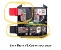
Do you even have a shunt?That fuse in the lynx shunt is going to see 100% of the system current.


Do you even have a shunt?That fuse in the lynx shunt is going to see 100% of the system current.
It appears that you have no experience with this particular shunt. No current will flow across it until a fuse is installed.Do you even have a shunt?

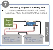
This is simply a shunt in a form factor that will attach to the Lynx system. Current flow is not necessary across the red terminals. Voltage is necessary to power the shunt. All current flow is across the negative (black) only. It is installed on the end and not the middle so positive current can power the shunt itself but the entire 1000a bus current is not intended to flow through the Red lugs. The ENTIRE negative current must flow through the shunt (black lugs). It functions and is wired the exact same way as any other shunt.It appears that you have no experience with this particular shunt. No current will flow across it until a fuse is installed.
The Lynx Shunt manual says the fuse is the main system fuse and gives this diagramThat is totally incorrect see my explanation above. I have one and so do hundreds of others. No, absolutely no shunt is fused for the loads or rated current flow. The only fused connection for ANY shunt is for the power lead to power the shunt itself.


Not using the positive side of the Lynx Shunt kinda defeats the purpose of the whole integrated lynx system.This is simply a shunt in a form factor that will attach to the Lynx system. Current flow is not necessary across the red terminals. Voltage is necessary to power the shunt. All current flow is across the negative (black) only. It is installed on the end and not the middle so positive current can power the shunt itself but the entire 1000a bus current is not intended to flow through the Red lugs. The ENTIRE negative current must flow through the shunt (black lugs). It functions and is wired the exact same way as any other shunt.
By all means, please continue to demonstrate that you have no experience with this product. I won't get in your way again. I'm just here to help the OP.This is simply a shunt in a form factor that will attach to the Lynx system. Current flow is not necessary across the red terminals. Voltage is necessary to power the shunt. All current flow is across the negative (black) only. It is installed on the end and not the middle so positive current can power the shunt itself but the entire 1000a bus current is not intended to flow through the Red lugs. The ENTIRE negative current must flow through the shunt (black lugs). It functions and is wired the exact same way as any other shunt.
6. Installation
www.victronenergy.com

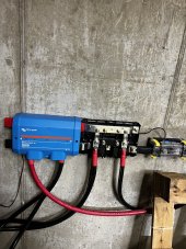
I didn’t say you didn’t use the positive it is used as a power source for the shunt itself. For instance in my installation this shunt would add on to the end of my Power Ins approximately where I installed a regular Victron Shunt. My negatives from the shunt would attach on the black lug. The positives from my inverter would attach to the positive buss of the Power In just like I have them wired. This shunt is no different than my Victron shunt and is wired the exact same way. Notice no positive is attached to the shunt. No big fuses and I went with the 500a shunt because my max inverted load or charge is 285 amps. You do as you wish but you will be unable to find fuses larger than 500 or do amps so that is your rate limiting factor. Mine would be my 500a shunt but they also sell it in 1000a shunt no fuses required.Not using the positive side of the Lynx Shunt kinda defeats the purpose of the whole integrated lynx system.
And your experience is? At least I own and use the product. Any suggestions on OPs question of how he retains 1000amps current flow through his buss? Crickets.By all means, please continue to demonstrate that you have no experience with this product. I won't get in your way again. I'm just here to help the OP.
A system with one of these will not work unless a fuse is installed.
Here's the pertinent page from your link.
View attachment 131351
Oh my gosh. What's next with you? This doubling down thing you're doing is terribly unproductive and no one is even mentioning Sol-Ark. May I suggest that you look into some healthier hobbies? Perhaps lay off the drink just a bit? Buuurrp...And your experience is? At least I own and use the product. Any suggestions on OPs question of how he retains 1000amps current flow through his buss? Crickets.
Per my instructions he retains his 1000 amps current and if he takes my other suggestion he could save himself $3-500.00 as a bonus.
We will all be here here waiting on the picture of YOUR lynx shunt.Yes you forgot to blame Victron for a faulty product
Maybe your sponsor can help you? Remember, the first step is admitting you have a problem.So answer the original question and quit whining. How can you run a full 1000 amps through the Lynx Shunt?
Projection as usualMaybe your sponsor can help you? Remember, the first step is admitting you have a problem.
What? Buurp...Can’t answer figures. I clearly stated my components. I answered the Ops question and then you chimed in 10 posts no answer. At least I made some recommendations that will work. Must be tiring hijacking post to grind your ax.
There is treatment for thatWhat? Buurp...
And still waitingWe will all be here here waiting on the picture of YOUR lynx shunt.
Still waiting....too soon?