diy solar

diy solar

Planing to use Victron lynx 1000A Shunt but can only find fuses up to 800A

That is totally incorrect see my explanation above. I have one and so do hundreds of others. No, absolutely no shunt is fused for the loads or rated current flow. The only fused connection for ANY shunt is for the power lead to power the shunt itself.
I am still working to make sense about all of this.

This is from the Victron website.
  • Lynx Shunt VE.Can - A positive busbar with a space for a main system fuse and a negative busbar with a shunt for battery
    monitoring. It has VE.Can communication for monitoring and setup with a GX device.

My interpretation is that the lynx shunt product has three functions:
1. Positive busbar (where my questions have been directed)
2. Negative busbar with a shunt for battery
monitoring
3. It has a VE.Can communication for monitoring and setup with a GX device

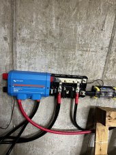
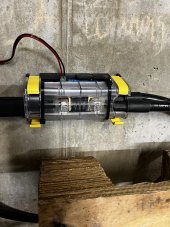
I've created a bit of a slide set to layout my understanding of how Victron explains their Shunt. From what I can see, it sits in the middle of the lynx distribution system. I am building this for a boat and need to follow the advice of my ABYC certified electronics engineer. He needs to sign off on the design for insurance purposes. For me this NOT about saving a few dollars, but doing it correctly.

BTW, these are pictures of the hardware siting on my desk. Screenshot 2023-01-24 at 22.28.55.png

1. lynx system schematic.png2. lnyx schematic with actual picture overlay.png3. actual lynx with labeling.png4. actual lynx with labeling alt. view.png
 
Sorry everyone. It looks like my post was redundant and late to the party. I had set up my reply and forgot to hit send. Only after hitting send did I learn about everyone else's posts. ughh...
 
Charitable interpretation is they misunderstood the question.
Less charitable interpretation is they pretended to misunderstand the question.

The way to make this work is put a nickel plated copper stunt double in place of the shunt fuse.
The stunt double should be the same dimensions as the busbar.

Each battery should be fused as close as possible to the positive terminal.
Each branch circuit should also be fused at the distributor.
The fuse in the shunt is kinda pointless in a properly fused system anyway.
Especially in a 24 volt or higher system with LFP batteries.

I do not disagree. This application is for my boat. I'm working with an ABYC certified installer that happens to be an electrical engineer. The rub is that I need to use UL components and use an ABYC certified technician for insurance reasons. He happens to have used this set up on another boat, so suggested these components, without seeing the boat. It's not very expensive and when I priced other components separately they were more expensive. I totally agree that each power source needs its own fuse, along with each branch circuit. I am dealing with some space constraints so need to reasses the design anyways.

Thanks for the thoughtful reply.

I appreciate everyone's willingness to engage and share their input!
I think you have discovered a small flaw in this device. As I see it as currently configured the rate limiting factor is the central fuse.

1: So you can choose to put the biggest one you can find and keep some spares. Your current will be limited to your fuse size but no where near the 1000 amp rating.

2: You could fabricate a piece of bus bar to jump the lugs and eliminate the fuse altogether which would not jeopardize anything as you surely will have other fuses or breakers in place to cover your batteries and inverter. So this fuse is redundant and not necessary.

3: You could extend the two leads outside of the shunt install a T class fuse and holder which actually would increase your safety factor by a large margin.

4: You could rearrange the sequence of your equipment putting the shunt on the end instead of in the middle. This would work well as you wouldn’t be running all of your positive current through the shunt and it would just receive the voltage to operate the shunt.

5: You could eliminate the Lynx Shunt attach the Power Ins and the distributor together and add a Victron Smart shunt to the end (similar to what I did).

I think any of the above would be acceptable and pass inspection. I almost bought that shunt for a cleaner install but I was took cheap at the time. Now I am glad I didn’t. I know I mentioned this earlier but IMO the distributor is unnecessary for its cost. I was able to turn my Power Ins into distributors with a simple modification and saved myself several hundred dollars. I think if you want to utilize what you have I would personally choose option 3. It gives you real benefit and safety margin. Class T fuses are available for over 1000 amps and are far superior to MEGA fuses.


Attachments

  • 67BE528D-0D9C-49B4-8F2F-E6B0D3C18F8D.jpeg
    67BE528D-0D9C-49B4-8F2F-E6B0D3C18F8D.jpeg
    1.5 MB · Views: 9
  • 20C728CF-B0F3-4589-A2C0-44A1F5B41623.jpeg
    20C728CF-B0F3-4589-A2C0-44A1F5B41623.jpeg
    1.2 MB · Views: 10
I do not disagree. This application is for my boat. I'm working with an ABYC certified installer that happens to be an electrical engineer. The rub is that I need to use UL components and use an ABYC certified technician for insurance reasons. He happens to have used this set up on another boat, so suggested these components, without seeing the boat. It's not very expensive and when I priced other components separately they were more expensive. I totally agree that each power source needs its own fuse, along with each branch circuit. I am dealing with some space constraints so need to reasses the design anyways.

Thanks for the thoughtful reply.

I appreciate everyone's willingness to engage and share their input!
I think you have discovered a small flaw in this device. As I see it as currently configured the rate limiting factor is the central fuse.

1: So you can choose to put the biggest one you can find and keep some spares. Your current will be limited to your fuse size but no where near the 1000 amp rating.

2: You could fabricate a piece of bus bar to jump the lugs and eliminate the fuse altogether which would not jeopardize anything as you surely will have other fuses or breakers in place to cover your batteries and inverter. So this fuse is redundant and not necessary.

3: You could extend the two leads outside of the shunt install a T class fuse and holder which actually would increase your safety factor by a large margin.

4: You could rearrange the sequence of your equipment putting the shunt on the end instead of in the middle. This would work well as you wouldn’t be running all of your positive current through the shunt and it would just receive the voltage to operate the shunt.

5: You could eliminate the Lynx Shunt attach the Power Ins and the distributor together and add a Victron Smart shunt to the end (similar to what I did).

I think any of the above would be acceptable and pass inspection. I almost bought that shunt for a cleaner install but I was took cheap at the time. Now I am glad I didn’t. I know I mentioned this earlier but IMO the distributor is unnecessary for its cost. I was able to turn my Power Ins into distributors with a simple modification and saved myself several hundred dollars.

Here is a link

 
After reading this whole string, I'm almost afraid to post, but have you looked at the specs on the 800A CNN fuse? This is the Little fuse time current characteristic curve. a 800A CNN from littelfuse will sustain 1,600A for 2 seconds, 1,400 A for 6 seconds and 1,200A for 100 seconds. Sounds like that would be within your initially described scenario.

Good luck, interested to hear what you end up with.

 
Back
Top