diy solar

diy solar

Pleasantly unexpected function of Growatt 12kW LF inverter in conjunction with a grid tie.

If you are motivated you may still be able to make it work safely by adding a contactor to the output of your grid-tied inverter and DIY a controller to only turn on the contactor if you are 1) on grid or 2) off grid and your battery SOC (assuming your BMS provides such info over RS484 or similar interface) is less than some safe threshold (e.g. <80%). Similarly, when off grid the contactor should turn off whenever the battery SOC is nearly full (e.g. >90%).
That isn't a bad idea. What I wish I could do is have the Growatt and Solaredge inverters communicate since they both have RS485 ports.
 
Upon further research, the Growatt LF inverters DO support AC coupling, but DO NOT support frequency shifting, so manual disconnection of the grid tie input or managing of loads will be required. So it is like 90% win for me, since my 3.15 kW array maxes at about 23kWh per day, and I have a 36kWh battery bank, so in a sustained grid-down situation my battery level will never hit 100% without me doing some serious load management. My daily average consumption without charging the cars is about 1kWh/hr.
 
You can add a dump load charge controller like they use in wind/hydro as a backup before the BMS kicking in. I think there is a menu option to turn on dry contacts in the inverter as well, so you could use a relay/ssr to put some load on as well.
 
I did see an interesting event recently when running ac coupled where the Growatt started throttling the PV input as the battery got to 95% and then at about 97% I saw one phase had briefly shut off, which caused my grid-tied inverter to shut off. I thought that may have been intentional.

I recently added another 14kWh of LF280k's to the battery bank, bringing my total to just over 50kWh, which are not able to fully charge right now even with 8kW of AC and DC coupled solar because we have 102F temperatures today and the AC in the house and garage are going like crazy. Maybe once it cools down I will be able to safely experiment with that.
 

Attachments

  • Screenshot_2022-06-27-17-21-31-36_40deb401b9ffe8e1df2f1cc5ba480b12.jpg
    Screenshot_2022-06-27-17-21-31-36_40deb401b9ffe8e1df2f1cc5ba480b12.jpg
    62.7 KB · Views: 13
There are definitely settings where you can choose how to charge batteries - AC/PV or just Solar, and in what order. You can also choose what order your inverter will power your house depending on your use. A lot of people in California etc charge batteries during 'cheap power' times and use batteries during 'expensive power' times. Definitely a built in function - if you have any questions let us know we are very versed with Growatt.
... except when it comes to safely wiring their ac input to the grid. :mad:
 
Upon further research, the Growatt LF inverters DO support AC coupling, but DO NOT support frequency shifting, so manual disconnection of the grid tie input or managing of loads will be required. So it is like 90% win for me, since my 3.15 kW array maxes at about 23kWh per day, and I have a 36kWh battery bank, so in a sustained grid-down situation my battery level will never hit 100% without me doing some serious load management. My daily average consumption without charging the cars is about 1kWh/hr.
Wouldn't it just be easier and probably more safe to just input the AC into the GW inverter AC inputs instead of having it backfeed on the GW output?

You have the battery size needed for all of your needs in grid down. Having 2 AC outputs tied together is just asking for trouble. You would be better served with a transfer switch for the PV where it feeds the grid tie except when the grid goes down. When grid is down, the transfer switch will allow PV to be switched to the GW PV inputs.
 
I did see an interesting event recently when running ac coupled where the Growatt started throttling the PV input as the battery got to 95% and then at about 97% I saw one phase had briefly shut off, which caused my grid-tied inverter to shut off. I thought that may have been intentional.

I recently added another 14kWh of LF280k's to the battery bank, bringing my total to just over 50kWh, which are not able to fully charge right now even with 8kW of AC and DC coupled solar because we have 102F temperatures today and the AC in the house and garage are going like crazy. Maybe once it cools down I will be able to safely experiment with that.
That is most likely an actual fault condition, because it wasn’t designed for AC coupling (Probably over DC or AC voltage).
 
... except when it comes to safely wiring their ac input to the grid. :mad:
Signature Solar has explained and confirmed all the internal workings of the unit on several posts. They have been very clear that they will not provide wiring at an individual capacity for a number of reasons. If you remain uncertain of how to connect it given the information about the internal workings, it is recommended to work with someone who feels comfortable with the set up. Signature Solar has always stated that the equipment they sell should be installed by a licensed electrician or by a qualified individual who feels confident in their ability.
 
Wouldn't it just be easier and probably more safe to just input the AC into the GW inverter AC inputs instead of having it backfeed on the GW output?

You have the battery size needed for all of your needs in grid down. Having 2 AC outputs tied together is just asking for trouble. You would be better served with a transfer switch for the PV where it feeds the grid tie except when the grid goes down. When grid is down, the transfer switch will allow PV to be switched to the GW PV inputs.

The reason to use grid tie during a utility outage is to get power from the solar array. If you put the grid-tie unit on the input side of the growatt, then in a utility outage you have your battery power and that's it - regardless of how much sun you have, the solar panels are inert.

Putting it on the output allows the grid tie to work correctly whether there's utility power or not. The growatt doesn't care if power is going from the outpute to the input in bypass mode, and in inverter mode it charges its own batteries from the output to keep the micro-grid stable.

In other words, the growatt acts as a full-service power grid, both giving energy as needed, and absorbing energy as required.

The one downside is that while it does perform this way, it's not rated nor advertised as such - and so far I haven't seen anyone do a deep analysis of it to determine efficiency, or if there are long term negative effects. I do know that the manufacturer and suppliers I've talked to about this will consider the warranty void if a grid tie inverter is connected to the output, they consider it an invalid installation.

As pointed out, though, it does NOT use the charge settings when it's charging the batteries from the output. It will overcharge the batteries if an external system doesn't kick in and reduce the power going into the growatt - either by consuming more of the energy, modulating the grid-tie output, or disabling the grid tie altogether.

If your BMS has configurable outputs, I'd suggest setting one up that indicates when the batteries are getting close to the point where they will shut off to protect themselves. Have that disconnect the grid-tie from the micro-grid using a latching relay or time delay relay so it has to be either manually reset, or it has to wait an hour or two after the batteries stop complaining to turn back on, and if the batteries do shut down at least the growatt only has to deal with shutdown under load, and not under backfeed - and that should be a relatively safe situation.

If your BMS isn't configurable, you can probably just monitor the battery voltage - anything higher than 54v (a bit less than 3.4v/cell) and you shut off the grid tie, and run off battery for awhile. Make sure you have a time delay or hysteresis so it doesn't switch on and off rapidly under sunny conditions - given your loads and power consumption I expect you'd find an hour or two cycling to be safe. These devices are cheap and readily available:


Set the voltage range, then set the startup time delay to maximum (16 minutes for this one) or use a time delay relay to extend that.
 
The reason to use grid tie during a utility outage is to get power from the solar array. If you put the grid-tie unit on the input side of the growatt, then in a utility outage you have your battery power and that's it - regardless of how much sun you have, the solar panels are inert.

You missed the second part about a transfer switch on the PV...........
Putting it on the output allows the grid tie to work correctly whether there's utility power or not. The growatt doesn't care if power is going from the outpute to the input in bypass mode, and in inverter mode it charges its own batteries from the output to keep the micro-grid stable.

In other words, the growatt acts as a full-service power grid, both giving energy as needed, and absorbing energy as required.

The one downside is that while it does perform this way, it's not rated nor advertised as such - and so far I haven't seen anyone do a deep analysis of it to determine efficiency, or if there are long term negative effects. I do know that the manufacturer and suppliers I've talked to about this will consider the warranty void if a grid tie inverter is connected to the output, they consider it an invalid installation.

As pointed out, though, it does NOT use the charge settings when it's charging the batteries from the output. It will overcharge the batteries if an external system doesn't kick in and reduce the power going into the growatt - either by consuming more of the energy, modulating the grid-tie output, or disabling the grid tie altogether.

If your BMS has configurable outputs, I'd suggest setting one up that indicates when the batteries are getting close to the point where they will shut off to protect themselves. Have that disconnect the grid-tie from the micro-grid using a latching relay or time delay relay so it has to be either manually reset, or it has to wait an hour or two after the batteries stop complaining to turn back on, and if the batteries do shut down at least the growatt only has to deal with shutdown under load, and not under backfeed - and that should be a relatively safe situation.

If your BMS isn't configurable, you can probably just monitor the battery voltage - anything higher than 54v (a bit less than 3.4v/cell) and you shut off the grid tie, and run off battery for awhile. Make sure you have a time delay or hysteresis so it doesn't switch on and off rapidly under sunny conditions - given your loads and power consumption I expect you'd find an hour or two cycling to be safe. These devices are cheap and readily available:


Set the voltage range, then set the startup time delay to maximum (16 minutes for this one) or use a time delay relay to extend that.
 
I don't want this to come off like I am some kind of doom and gloom guy here, but this might be a bit dangerous.

AC coupling grid tie inverters to work off grid from an inverter is becoming a desirable feature. If a battery hybrid inverter can safely do it, then the manufacturer will call it out and know they can charge more if it can do it. When they come right out and tell you it will void the warranty, I would call that a red flag to NOT do it. The fact that it appears to work on short term tests does not mean it is safe to do it long term.

My Schneider inverter has some very specific setup requirements to work in AC coupled mode. Every inverter that supports this has limitations on how much solar can be connected. And they all warn that the battery bank can be subjected to the full charging power of the entire solar array.

When you also add in the lack of any ability to limit charging on it's own, you are really moving into dangerous territory. Any time you are relying on another device to control thing, you are adding more risk. In my system, I have a quality PLC adjusting my charge and grid sell current. It has crashed twice in about a year. In both cases, it only failed to start charging the battery bank. Not too big of a deal. But if it was controlling charge current and it crashed before the batteries became full, it could be a big problem. If the BMS has to open the battery charge path while it is back feeding power, the DC bus voltage in the inverter could certainly go high enough to damage itself. Imaging driving a car at full throttle, and just pushing in the clutch pedal. When you remove the load, things can go bad fast.
 
Signature Solar has explained and confirmed all the internal workings of the unit on several posts. They have been very clear that they will not provide wiring at an individual capacity for a number of reasons. If you remain uncertain of how to connect it given the information about the internal workings, it is recommended to work with someone who feels comfortable with the set up. Signature Solar has always stated that the equipment they sell should be installed by a licensed electrician or by a qualified individual who feels confident in their ability.
Per Growatt spf6000t dvm; also applies to the spf12k
I seem to recall Signature Solar offering to let me 'return the unit'. I am not interested in paying exorbitant shipping and restocking fees on this product, even if it cannot perform as advertised. Let's get to the first sentence in bold. If you have replied to the following June16 email answering both questions, my apologies, but Signature Solar's reply did not make it to my inbox,

so I will simply ask again;

does the Growatt spf6000t dvm have any internal safety measure to ensure its internal transformer does not become overloaded from trying to balance unbalanced loads placed on the utility's transformer, to which the Growatt's ac input is wired, and what is/are it/they?

Per the second statement in bold ... seriously ... you are targeting the diy market with your sales tactics! and without proper documentation, even a licensed electrician is kept guessing as to what is, and is not safe, with the products you sell.

How much longer will I have to wait for that answer Richard?

Apologies to the op for this ot.


1657832679721.png
 
There are a lot of people on this forum who are not licensed electricians who feel perfectly competent in using the inverters they purchase, installing them, and running them without concern. It is SS's recommendation as a company to make sure that it is installed by a professional to ensure that it is done correctly and safely. I'm sure there are a large % of users here who feel that they could install the unit safely with the information that has been provided. I strongly urge anyone who doesn't feel comfortable or competent in working with this equipment to turn to someone who is, for your own safety and the safety of those around you and your property. I didn't see an email to me sent on June 16th, I'm assuming its the one you sent to Peyton, but I've forwarded this specific question to a Growatt engineer and hope for a reply soon. Signature Solar isn't Growatt, and with that being said we must await their technical answer on specific questions like this, or else wait until we have the time and resources to get down to board level schematics and looking up chip operations to attempt and find the answers ourselves.

There are a number of users on this forum using Growatt SPFXXXX and maybe they can chime in about their experience and comfort level with the units.
 
You missed the second part about a transfer switch on the PV...........

I did miss that, sorry. The residential solaredge inverters have a nominal DC input voltage of 380-400VDC, so even if the OP got the newer SPF12000T with 250V input (vs the older model with a 150VDC limit), reconfiguring the solar array for the growatt would probably be more trouble than it's worth. It could be done, though. I'm guessing it's a single string of 10 panels, 315w each, with a max VOC around 450v.
 
  • Like
Reactions: Zwy
I did miss that, sorry. The residential solaredge inverters have a nominal DC input voltage of 380-400VDC, so even if the OP got the newer SPF12000T with 250V input (vs the older model with a 150VDC limit), reconfiguring the solar array for the growatt would probably be more trouble than it's worth. It could be done, though. I'm guessing it's a single string of 10 panels, 315w each, with a max VOC around 450v.
Good info. I'm not very familiar with grid tie and optimizers and the PV voltage of the systems. If the PV array is in that voltage range, the EG4 would be an inverter better suited for this purpose.
 
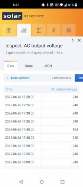
As an update to this, just for fun, I did shut off my main breaker and ran off-grid with the Growatt 12K and my AC coupled Solar Edge grid-tied system for 100 hours. It ran perfectly, even charging the battery at nearly 7kW at times.

Part of why I added the extra capacity is so that it would dramatically lower the chance of my battery overcharging in this situation. Though, I am still looking into ways to shut off the grid tied inverter based on battery voltage. It may be a moot point, as I am going to have a 21 panel solar pergola installed on another Solaredge inverter, this time likely a 7600W. It will be built using the 12 panels that are currently DC coupled to the Growatt. I would never feel comfortable attempting to backfeed 11kW+ through this inverter, so it will still likely remain an emergency backup only. The 7600W inverter will be installed on a line side tap, which will make that power unavailable to me once I turn off my main breaker in a grid-down situation.

Right now the Growatt is wired to a pair of taps that splits off to a sub panel in the outside of my house that runs my 24k BTU main AC and a 9K BTU mini-split, as well as my house refrigerator. The other line of that tap goes to my backfeed breaker with a generator interlock. The 12 panels on my lawn have exclusively been used to power the AC and fridges. It has been operating like this continuously for a month or so, just trying to lower my power bill. Having it set up like this also allows me to have the Growatt hooked to the grid as a backup, and it will automatically switch to grid mode when the battery reaches 20%.
 
Last edited:
Back
Top