diy solar

diy solar

Please advise a true NEWB on 24V system

2manyquestions

New Member
Joined
Jul 22, 2021
Messages
26
Hello, everyone.

It appears I am much more of a newb than others here, hence my post in the newcomer section, and my forum handle. On other forums (RC planes, RC cars, and others), I started as a complete newb, some members patiently answered my questions, and I was able to “give back” to other newbs after I gained some experience. I hope to do the same here.

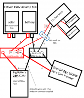
I have attached a mockup of the component wiring diagram I envision, based on my beginner brain. Numbers represent wire gauges, and the one number in a square block is a fuse to the SCC. If I am wrong with how I intend to wire this up, or you have a cleaner way of doing it, your suggestions would be very much appreciated! Please make sure to DUMB DOWN your suggestions for me.

Thus far, I have read through Will’s book on DIY Mobile Solar Power (1st edition) and watched several of his beginner videos.

So, here are my questions:
  • My Big Battery is 24V battery and my solar charge controller and inverter are compatible with this voltage. Is it ok to use a wire gauge chart for a 12V system?
  • My battery comes with an integrated 300 amp fuse…is this in place of the bolt on fuse that typically goes on the positive battery terminal?
  • My Big Battery 24V 202AH battery came with a 175 amp Anderson connector with 6 AWG 105 degree C wires. I am assuming the ones supplied are ok?
  • In some drawings in Will’s book, several (+) or (-) wires “meet together” and continue along one wire, but I don’t exactly know how they are all connected to one. How would that be done for negative wires? And for positive wires (bolt on fuse)? I do not know how to do this.
  • Since I don’t know the answer to question 4 above, I thought I could use one main negative bus and one main positive bus to join the different positive and negative wires per my diagram. Is that ok? If I were to use the bus bars per my diagram, and since they would provide up to 166 amps to the inverter (4000W surge), 40 amps to my charge controller, and maybe another 25 amps to the fuse block, would each bus need to be rated at least 250 amps?
  • I realize I will need a 24V to 12V step down converter to power my 12V appliances. Anyone want to recommend a good one? Where is the best place to wire that in?
  • The Blue Sea Systems fuse block linked from Will’s website (with negative and cover) appears to be able to take the negative lead from the appliances. So, it appears there is no need to connect to a separate negative bus, correct?

Thank you so much!!
 

Attachments

  • Wiring diagram cropped.pdf
    80.3 KB · Views: 35
Hello, everyone.

It appears I am much more of a newb than others here, hence my post in the newcomer section, and my forum handle. On other forums (RC planes, RC cars, and others), I started as a complete newb, some members patiently answered my questions, and I was able to “give back” to other newbs after I gained some experience. I hope to do the same here.

I have attached a mockup of the component wiring diagram I envision, based on my beginner brain. Numbers represent wire gauges, and the one number in a square block is a fuse to the SCC. If I am wrong with how I intend to wire this up, or you have a cleaner way of doing it, your suggestions would be very much appreciated! Please make sure to DUMB DOWN your suggestions for me.

Thus far, I have read through Will’s book on DIY Mobile Solar Power (1st edition) and watched several of his beginner videos.

So, here are my questions:
  • My Big Battery is 24V battery and my solar charge controller and inverter are compatible with this voltage. Is it ok to use a wire gauge chart for a 12V system?
  • My battery comes with an integrated 300 amp fuse…is this in place of the bolt on fuse that typically goes on the positive battery terminal?
  • My Big Battery 24V 202AH battery came with a 175 amp Anderson connector with 6 AWG 105 degree C wires. I am assuming the ones supplied are ok?
  • In some drawings in Will’s book, several (+) or (-) wires “meet together” and continue along one wire, but I don’t exactly know how they are all connected to one. How would that be done for negative wires? And for positive wires (bolt on fuse)? I do not know how to do this.
  • Since I don’t know the answer to question 4 above, I thought I could use one main negative bus and one main positive bus to join the different positive and negative wires per my diagram. Is that ok? If I were to use the bus bars per my diagram, and since they would provide up to 166 amps to the inverter (4000W surge), 40 amps to my charge controller, and maybe another 25 amps to the fuse block, would each bus need to be rated at least 250 amps?
  • I realize I will need a 24V to 12V step down converter to power my 12V appliances. Anyone want to recommend a good one? Where is the best place to wire that in?
  • The Blue Sea Systems fuse block linked from Will’s website (with negative and cover) appears to be able to take the negative lead from the appliances. So, it appears there is no need to connect to a separate negative bus, correct?

Thank you so much!!
I will go through and answer your questions in my next post but here are my notes for your drawing.

Its crazy to have a 300a fuse on a 6 awg wire.
I have no idea why big battery would do that.
The fuse is supposed to give its life to protect the wire.
In this case the insulation will melt off the wire long before the fuse blows.

Your 24->12 volt converter is not shown

Its best practice to fuse the each load wire directly off the positive bus bar
that means inverter and fuse block
Suggest one of these https://www.bluesea.com/products/5196/MRBF_Surface_Mount_Fuse_Block_-_Common_Source
with some of these https://www.bluesea.com/products/category/15/42/Fuses/Marine_Rated_Battery_Fuses

the formula for fusing your inverter and sizing your battery capacity is

inverter continuous watts / .85 conversion factor / 24 volts low cutoff = 98.039215686 dc amps
98.039215686 dc amps / .8 fuse headroom = 122.549019608 fuse amps

You don't some to have any low voltage disconnect strategy.
That needs to be addressed.


122.549019608 amps is right on the hairy edge of what 6 awg is capable of.
I would love to know what Big battery were thinking.
 
Hello, everyone.

It appears I am much more of a newb than others here, hence my post in the newcomer section, and my forum handle. On other forums (RC planes, RC cars, and others), I started as a complete newb, some members patiently answered my questions, and I was able to “give back” to other newbs after I gained some experience. I hope to do the same here.

I have attached a mockup of the component wiring diagram I envision, based on my beginner brain. Numbers represent wire gauges, and the one number in a square block is a fuse to the SCC. If I am wrong with how I intend to wire this up, or you have a cleaner way of doing it, your suggestions would be very much appreciated! Please make sure to DUMB DOWN your suggestions for me.

Thus far, I have read through Will’s book on DIY Mobile Solar Power (1st edition) and watched several of his beginner videos.

So, here are my questions:
  • My Big Battery is 24V battery and my solar charge controller and inverter are compatible with this voltage. Is it ok to use a wire gauge chart for a 12V system?

There are 2 concerns.
The wire must be able to handle the anticipated amps including blowing the fuse.
Amps are not voltage dependent except as the system voltage doubles the amps required for a given power are halfed.

The other concern is voltage drop and that goes down as the voltage goes up.
Have a look at the link below and play with the calculator to get a sense of the scale and proportion.


  • My battery comes with an integrated 300 amp fuse…is this in place of the bolt on fuse that typically goes on the positive battery terminal?
Call Big battery and ask them what they are smoking.
Ask them why they put a 300 amp fuse on a 6 awg wire.
Please report back because that should be interesting.
Ask them if you can replace it with something appropriately sized.
If it was me I would replace with a 125 amp fuse.

  • My Big Battery 24V 202AH battery came with a 175 amp Anderson connector with 6 AWG 105 degree C wires. I am assuming the ones supplied are ok?
I would like to see them bigger.
Voltage drop is probably going to be a consideration.
The shorter the wire the better.
But they are just on the hairy edge assuming a 125 amp fuse.
  • In some drawings in Will’s book, several (+) or (-) wires “meet together” and continue along one wire, but I don’t exactly know how they are all connected to one. How would that be done for negative wires? And for positive wires (bolt on fuse)? I do not know how to do this.
Not sure I understand what you are saying.
  • Since I don’t know the answer to question 4 above, I thought I could use one main negative bus and one main positive bus to join the different positive and negative wires per my diagram. Is that ok? If I were to use the bus bars per my diagram, and since they would provide up to 166 amps to the inverter (4000W surge), 40 amps to my charge controller, and maybe another 25 amps to the fuse block, would each bus need to be rated at least 250 amps?
positive and negative busbars is a very common and imho good design pattern.
Have a look at the one I linked in my previous post.
4000 watts is the surge capacity of that inverter, which it can deliver for ~1 cycle of ac current.
It only matters to the marketing department.
  • I realize I will need a 24V to 12V step down converter to power my 12V appliances. Anyone want to recommend a good one? Where is the best place to wire that in?
Victron or Samlex.
Don't get the cheap crap off amazon if you need this to work.
  • The Blue Sea Systems fuse block linked from Will’s website (with negative and cover) appears to be able to take the negative lead from the appliances. So, it appears there is no need to connect to a separate negative bus, correct?
Yes you can connect the negative wires back to the negative busbar on the fuse block.
Suggest you make a new drawing with all the changes and we can all have another look.
This is an iterative process.
 
Last edited:
Hi, Joey.

Thank you for your answers to some of my questions and for the suggestion on fuse block/fuses and 24V to 12V converter - I will search for one. I also will work on a revised drawing over the next few days and share again.

I agree about the built-in fuse on the battery - it actually turns the supplied 6 gauge wires into the fuse. I will ask Big Battery and report back. Honestly, it was not until the batteries were in transit that I came across various issues with BigBattery (leaking cells, problems with BMS) that made me question my choice. Returning it would cost $190 to ship and $345 restocking fee. Hope I did not make a bigger mistake by keeping it.

The battery has a built-in BMS with a low voltage cutoff, so that is taken care of, if it works.

Anyway, I am not really sure what to do with the voltage drop calculator you had linked. At the very top, do I input the max discharge amps of the battery?

I am still needing some help with these questions, so if you, or anyone else can chime in on one or both, very much appreciated!
  • My Big Battery is 24V battery and my solar charge controller and inverter are compatible with this voltage. Is it ok to use a wire gauge chart for a 12V system?
  • Where is the best place to wire in a 24V to 12V converter? I guess it would be in the item's instructions...?
 
The battery has a built-in BMS with a low voltage cutoff, so that is taken care of, if it works.
A fet based bms is not designed to routinely disconnect a load at significant amperage.
If it has a contactor(big honking relay) then its ok but if its solid state its a disaster waiting to happen.

Anyway, I am not really sure what to do with the voltage drop calculator you had linked. At the very top, do I input the max discharge amps of the battery?
put 100 amps in the top box
put the round trip length for the wire between the battery and the big load
put 24 volts in the last box

It will show you what size wire you need to achieve your desired voltage drop
Shoot for 3% or less

Now go down and look at the table labeled Ampacity limits
Find the guage of wire that can handle 123 amps.
That table assumes pure copper wire with insulation rated to 105c
Since nobody in their right mind wants their wires to get that hot suggest you bump up the size a bit.
Unfortunately yours came with 6 awg wire.


I am still needing some help with these questions, so if you, or anyone else can chime in on one or both, very much appreciated!
  • My Big Battery is 24V battery and my solar charge controller and inverter are compatible with this voltage. Is it ok to use a wire gauge chart for a 12V system?
I answered that question.
The amount of power(watts) you can pass over a wire doubles when you double the system voltage at the same amperage.
Voltage drop decreases with increased system voltage.
  • Where is the best place to wire in a 24V to 12V converter? I guess it would be in the item's instructions...?

positive_busbar->fuse->24to12_converter->fuse->fuse_block->load
negative_busbar<-24to12_converter<-fuse_block<-load
 
Last edited:
Hi, Joey.

Thank you for your answers to some of my questions and for the suggestion on fuse block/fuses and 24V to 12V converter - I will search for one. I also will work on a revised drawing over the next few days and share again.

I agree about the built-in fuse on the battery - it actually turns the supplied 6 gauge wires into the fuse. I will ask Big Battery and report back. Honestly, it was not until the batteries were in transit that I came across various issues with BigBattery (leaking cells, problems with BMS) that made me question my choice. Returning it would cost $190 to ship and $345 restocking fee. Hope I did not make a bigger mistake by keeping it.

The battery has a built-in BMS with a low voltage cutoff, so that is taken care of, if it works.

Anyway, I am not really sure what to do with the voltage drop calculator you had linked. At the very top, do I input the max discharge amps of the battery?

I am still needing some help with these questions, so if you, or anyone else can chime in on one or both, very much appreciated!
  • My Big Battery is 24V battery and my solar charge controller and inverter are compatible with this voltage. Is it ok to use a wire gauge chart for a 12V system?
  • Where is the best place to wire in a 24V to 12V converter? I guess it would be in the item's instructions...?
You choose the gauge based on the amperage and distance regardless of voltage.

The 24>12 gets wired on the positive and negative 24V bus.
 
Sorry for my delay...life remains busy and I have been waiting for a response from Big Battery about whether I can replace the 300 amp fuse. I should be able to, but I wanted a response from them. Wrote an email first thing Monday morning, but no response as of yet (Tuesday night).

I am working on a revised wiring diagram, and hope to post one by tomorrow evening.
 
BigBattery never responded to my emailed question about the 300 amp fuse, so I don't know why they used that size, or what I would need to do to replace it. It is bolt-in, so I suppose I could simply swap it out.

Ok, finally got version 2 of my wiring plan done. Will it be the final? We'll see. Anyway, here are my questions/things I am not sure about:

1. Wire gauges are small black numbers next to wires...do they look ok?
2. I plan to use a Blue Sea MRBF Surface Mount Fuse block with "terminal" fuses for the positive side of things. Do those fuse sizes look correct?
3. I plan to use a 250 amp bus bar for the negative side of things.
4. I plan to use a 70 amp Victron Orion 24V to 12V step down converter. According to the online instructions, it has a single "common" negative terminal. Do I connect the negative wire from the 12V fuse block and the negative wire from the negative bus bar to this common negative?
5. I have an 80 amp fuse between the voltage converter and 12V fuse block. Do I need one between the voltage converter and MRBF fuse block - I figured with the "screw in" fuse in the MRBF, I don't need an inline fuse. Is that correct?

I think that is all my questions for now.

Input is appreciated! (pun intended)

Wiring diagram cropped 2.png
 

Attachments

  • Wiring diagram cropped 2.pdf
    149.7 KB · Views: 2
What is the current draw you expect from the battery? 6ga is only good for 70A. If you had a cable that was rated equal to the connector, the cable would be 1 or 2/0. You have 0 on the inverter but only 6 on the battery?

Is the Orion connected to an alternator? Seems you have it in place of a step down converter and I haven't seen Orions used for that?
 
Hey, Stepandwolf.

Expected current draw on my battery is a good way to approach this...I did not think of that. I would imagine the highest draw on the battery would be from an 1800W microwave on the inverter (so, at 24 volts, 75 amps?) and a few more amps from miscellaneous items like a small fridge on the 12V fuse block.

The battery came with 6 gauge leads on an Anderson connector, but I am confused about your 70A claim. According to the wire chart I have used, 6 gauge, at up to 4 foot length, is good for 150-200 amps. But, I was advised to change the fuse to 125A on the battery, and I suppose the 6 gauge wire can stay?

As far as the Victron, it does appear to be a step down converter:

I found a chart a while back that is pretty, easy to read, and makes things as clear as they can be. Further, its information matches everything else I have seen.

DC Wire Chart

Thanks for the heads up on that Orion. I wasn't aware of that model as the only Orions I knew of were for alternator use.
Going by the chart you provided, I need to "upgrade" the wire gauge for my setup. A bit more expensive, but will ensure minimal losses, so I will do that.

I am assuming that since there were no other comments, everything else looks "OK", aside from the wire gauges I have illustrated.
 
Pure copper 8 awg wire with 105C insulation is rated for 80 amps max.
The 100 amp fuse upstream of the 24->12 buck converter is too big.
40 amps would be fine.

8 awg between the buck converter and the fuse block is pushing it to the limit.
I don't think you want your wires getting hotter than boiling water.

The 100 amp fuse upstream of the inverter is too small.
2000 ac watts / .85 conversion factor * 1.12 ripple factor / 20 volts low cutoff / .8 fuse headroom = 164.705882353 fuse amps

6 awg wire is way too small for the 300 amp battery fuse.
 
Going by the chart you provided, I need to "upgrade" the wire gauge for my setup. A bit more expensive, but will ensure minimal losses, so I will do that.

I am assuming that since there were no other comments, everything else looks "OK", aside from the wire gauges I have illustrated.
Have you calculated the need for 70A DC? That is a lot. Most of the high draw appliances are 120V. I know I am putting in a 40A 24>12 for my installation, and it is Will's suggested converter model, but then each of us has to figure out their own power needs.

Five things I am accustomed to seeing which aren't in your drawing:
1. You don't show a master battery disconnect switch.
2. Since you aren't showing the wiring to the SCC from the panels, I don't know if you included a breaker between the panels and the SCC. It isn't so much to use it as a fuse, but as a disconnect to cut power off to the SCC when maintenance needs to be done or any other reason not to want power coming in from the panels. In my case, I bought a small box that contains a DIN rail and on the rail I have two 32A breakers. Breaker size being dependent on your panel power.
3. I am accustomed to seeing a shunt on the battery negative to read draw, such as a Victron BMV712.
4. I don't see a shore power connection or an ATS if you had shore power
5. Likewise, I don't see a battery charger. My Victron inverter contains the ATS and charger integrated into it.

As an aside, I was considering a Giandel myself. When they ignored my emails asking for some information I decided it wasn't the brand for me.

Best wishes!
 
Pure copper 8 awg wire with 105C insulation is rated for 80 amps max.
The 100 amp fuse upstream of the 24->12 buck converter is too big.
40 amps would be fine.

8 awg between the buck converter and the fuse block is pushing it to the limit.
I don't think you want your wires getting hotter than boiling water.

The 100 amp fuse upstream of the inverter is too small.
2000 ac watts / .85 conversion factor * 1.12 ripple factor / 20 volts low cutoff / .8 fuse headroom = 164.705882353 fuse amps

6 awg wire is way too small for the 300 amp battery fuse.
Thank you, Joey.

After viewing a different wire gauge chart from StepandWolf, I see where the 6 and 8 awg wire is too small, so I will upgrade accordingly.

Regarding the fuse upstream of the 24>12v, I could not find any info on current draw of this converter via online manual, so I just went "big" assuming if it can output as much as 70 amps, it must be drawing somewhere around that? I should receive the item today and will look again.

As far as the 300 amp fuse on the battery, I will change that to the 125 amp fuse you recommended and upgrade to 1 awg wire.

I have not seen such a complicated formula where you convert AC to DC watts. But I do know about adding 25% to calculated fuse size, or dividing by 0.8 as you do.
 
Regarding the fuse upstream of the 24>12v, I could not find any info on current draw of this converter via online manual, so I just went "big" assuming if it can output as much as 70 amps, it must be drawing somewhere around that?
70 amps at 12 volts is 35 amps at 24 volts plus 10% conversion overhead.

I have not seen such a complicated formula where you convert AC to DC watts.
@Hedges gets the credit... or the blame. ;)
 
Have you calculated the need for 70A DC? That is a lot. Most of the high draw appliances are 120V. I know I am putting in a 40A 24>12 for my installation, and it is Will's suggested converter model, but then each of us has to figure out their own power needs.

Five things I am accustomed to seeing which aren't in your drawing:
1. You don't show a master battery disconnect switch.
2. Since you aren't showing the wiring to the SCC from the panels, I don't know if you included a breaker between the panels and the SCC. It isn't so much to use it as a fuse, but as a disconnect to cut power off to the SCC when maintenance needs to be done or any other reason not to want power coming in from the panels. In my case, I bought a small box that contains a DIN rail and on the rail I have two 32A breakers. Breaker size being dependent on your panel power.
3. I am accustomed to seeing a shunt on the battery negative to read draw, such as a Victron BMV712.
4. I don't see a shore power connection or an ATS if you had shore power
5. Likewise, I don't see a battery charger. My Victron inverter contains the ATS and charger integrated into it.

As an aside, I was considering a Giandel myself. When they ignored my emails asking for some information I decided it wasn't the brand for me.

Best wishes!
StepandWolf,

Thank you for your suggestions. I figured I may need about 40A DC such as yourself, but wanted a little headroom just in case, so I went 70A for my converter.

1. I don't have a master battery disconnect. The BigBattery does have a built-in power button on the external case which I assumed would function the same.
2. I did not think about a breaker between panels and SCC, but will do that now, thanks for the suggestion! Can you include a pic of your setup, I don't quite understand.
3. Yes, a shunt/meter is next on my list!
4. No shore power connection as I did not anticipate needing that, if at all.
5. I have a separate AC to DC battery charger, but did not plan to wire it into the plan. Would not even know how.
 
Back
Top